
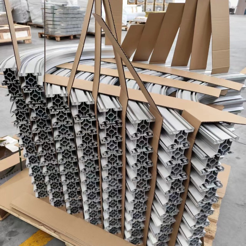
Aluminum Profile Bending
Irregular Compound Bending - 2 to 5 Bends in One Pass
Two to five continuous bends in one pass: why ±1° per bend accumulates to 26 mm at the end, tolerance budgeting, and when to machine after forming.
Product Details
Compound bending — two to five bends in one continuous pass, in more than one direction — is where tolerance arithmetic stops being intuitive. Each bend has its own angle tolerance, and those tolerances do not stay separate. They add up at the end of the part, and at the far end of a metre-long bracket a one-degree error per bend becomes a displacement measured in centimetres.
We form 2–5 section continuous bends, multi-angle compound bends and irregular forms in 6063-T5 and 6061-T6, with walls from 1 to 6 mm, single-section angles from 30° to 150°, an angle tolerance of ±1°, adjacent section spacing of ±0.5 mm and a cumulative overall length deviation of ≤±2 mm, in lengths up to 6,500 mm.
The arithmetic that matters
Consider a bracket with five bends, each at ±1°. If the errors happen to align — and in a production run some will — the accumulated error at the end of the part is five degrees. Over a 300 mm final leg, one degree of accumulated error moves the end by about 5 mm; five degrees moves it by 26 mm.
That is the difference between a part that bolts up and a part that does not, and it is not explained by "each bend is in tolerance".
| Bends | Each at ±1° | Worst-case accumulated angle | End displacement over a 300 mm leg |
|---|---|---|---|
| 2 | ±1° | 2° | ~10 mm |
| 3 | ±1° | 3° | ~16 mm |
| 5 | ±1° | 5° | ~26 mm |
So a drawing that specifies five bends at ±1° and also requires the part to fit an assembly is over-constrained, and the ±1° is not the useful number. What the assembly needs is a positional tolerance on the interfaces, and that has to be converted backwards into a per-bend allowance.
Budget the tolerance from the ends, not from the die
The right way to specify a multi-bend part is to start with what the assembly needs and work backwards.
- State the interface positions. The mounting faces, the hole patterns, the points where the part connects to something else — each with the tolerance the assembly can tolerate.
- Convert to an angular budget. A positional tolerance of ±2 mm at the end of a 300 mm leg corresponds to an accumulated angle of about ±0.4°. That is the total budget for all the bends in that leg, not per bend.
- Divide the budget across the bends. Five bends share 0.4°, so each needs to be within roughly ±0.08° — which is ten times tighter than ±1°, and it tells you immediately that the design or the process has to change.
That conclusion is uncomfortable and it is the honest one. Either the interface tolerance can be relaxed, or the part needs a fixture-checked assembly, or the critical interfaces have to be machined after forming so their position is set by the machine rather than by the accumulated bend error.
The third option is the usual answer for a precision bracket: form the bends to a workable ±1°, then machine the mounting faces and holes from a datum on the formed part. The bends become approximate and the interfaces become exact, which is the correct division of labour.
Section spacing: the error that moves the bends
On a multi-bend part, the distance between bends is as important as the angles, and it is easy to overlook why. The material between two bends is a fixed length. If the first section is formed 0.5 mm short, the material has to come from somewhere, and it comes from the next section.
The result is that a spacing error propagates forward: each bend sits slightly off position, and the error accumulates along with the angle error. A ±0.5 mm spacing tolerance on five sections can put the last bend 2 mm out of position before any angle error is added.
So the spacing tolerance and the accumulated length tolerance are linked, and they should be specified together. The ±2 mm cumulative figure exists for exactly this reason: it is the budget that the individual spacing tolerances have to fit inside.
Bend direction changes: the harder case
| Form | What it is | Where it gets difficult |
|---|---|---|
| 2 sections, same direction (U) | Two bends, both the same way | Parallelism of the two legs |
| 2 sections, opposite (Z) | Two bends in opposite directions | The offset dimension between the two legs |
| 3 sections, compound | Bends in more than one plane | Out-of-plane rotation; the part no longer lies flat |
| 4–5 sections, continuous | Complex multi-section geometry | Accumulated error in three dimensions; needs a checking fixture |
The step from two dimensions to three is the real threshold. A U or a Z bend lies in one plane and can be checked on a surface plate with a height gauge. A three-section compound bend does not — the part can be correct in two projections and wrong in the third, and the only practical check is a checking fixture or a CMM program built from the model.
If your part has bends in more than one plane, plan for a checking fixture. Without one, the part is inspected by whether it fits, which is a late and expensive way to find out.
Specifications
| Item | Reference value |
|---|---|
| Sections per part | 2–5 continuous bends |
| Section types | Multi-cavity, asymmetric, irregular profiles |
| Wall thickness | 1–6 mm |
| Single-section angle | 30°–150° |
| Angle tolerance | ±1° per section |
| Adjacent section spacing | ±0.5 mm |
| Cumulative length deviation | ≤±2 mm |
| Maximum length | 6,500 mm |
| Alloys | 6063-T5, 6061-T6 |
| Equipment | CNC press brakes, CNC machining centres |
| Downstream | CNC milling, drilling, tapping, cutting |
| Surface treatment | Anodising, powder coating |
| Standard | GB/T 6892-2023, ISO 9001 |
Supporting a multi-cavity section through several bends
On a multi-cavity profile, each bend needs the cavities supported or they collapse. Through a continuous pass, that support has to follow the section from one bend to the next, and that is a tooling problem rather than a forming one.
Three approaches:
Mandrel through the whole length. Works where the cavities are straight through-cavities and the mandrel can be withdrawn along the part after forming. It is the most reliable and it limits the section geometry.
Segmented filler. A low-melting filler fills the cavities, the part is formed, and the filler is melted out. It works on any geometry and it adds a per-part process step.
Die support only. A close-fitting die supports the outside and the cavities are left unsupported. This works on a thick wall or a rigid cavity and fails on a thin one.
The choice is set by the section, and it should be decided before the part is quoted, because it determines whether the part is feasible at all.
Where it does not fit
- The part has tight interface tolerances and four or more bends. The accumulated error exceeds what the bends can deliver. Machine the interfaces after forming, or split the part into an assembly.
- The drawing gives ±1° per bend and a tight positional requirement at the end. That is over-constrained. Get a positional tolerance stated instead, and let the process be planned against it.
- The section is a thin-wall multi-cavity and the bends are close together. The support cannot be re-established between bends, and the cavities collapse. Reduce the bend count or change the section.
- Bends are in three dimensions and there is no checking fixture. The part cannot be verified. Budget for the fixture or expect a fit-and-see outcome.
- Any bend is at 150° or beyond, in a tight space. The die and the part interfere with each other. That is a different tooling problem and may be a welded corner.
- The alloy is 6061-T6 with bends near the strain limit. Each bend is a risk, and with three bends the chance that one cracks is three times higher. Bend in T5 for multi-bend parts where the strength allows.
What to send for a quote
Send the profile drawing, the formed-part drawing with every bend dimensioned and the interface positions toleranced, the alloy and temper, the quantity, and whether the bends are in one plane or three. Tell us which dimensions are functional — that is what the tolerance budget has to be built around.
We will reply with a tolerance budget: what the per-bend tolerance has to be to meet your interface requirement, whether that is achievable, and if not, which interfaces we would machine after forming. We will also say whether a checking fixture is needed and what it would cost.
FAQ
What tolerance can you hold on a multi-bend part?
Reference ±1° per bend, ±0.5 mm on adjacent spacing and ≤±2 mm cumulative length. Those are capability references per feature. The value on your order is set by your drawing, and on a multi-bend part the number that actually matters is the cumulative one: we will convert your interface tolerance into a per-bend budget and tell you in writing whether the bends can meet it or whether the interfaces should be machined after forming.
What does 2–5 section continuous bending mean?
Two to five bends formed in one continuous pass on the same profile, without releasing and re-datuming the part between bends. Continuous forming matters because re-clamping a part introduces a new positioning error at every setup, and those errors add to the bend errors.
How is cavity collapse prevented on a multi-cavity profile?
By supporting the cavities through the bend: a mandrel through a through-cavity, a low-melting filler for a complex or blind cavity, or a close-fitting die where the wall is thick enough to resist. The method has to be selected from the section drawing before the part is quoted, because it decides whether the part can be made at all.
Why does my part not fit even though every bend is in tolerance?
Because tolerances accumulate. Five bends each within ±1° can put the end of the part 26 mm out over a 300 mm leg. The part is in tolerance feature by feature and out of position as an assembly. The fix is either a positional tolerance on the interfaces or machining the interfaces after forming.
Can the bends be in different directions?
Yes, including in different planes. The step from one plane to three is the significant one: a planar part can be checked on a surface plate, a three-dimensional one needs a checking fixture or a CMM program. Plan for the fixture if the part has out-of-plane bends.
How is it priced?
On the number of bends, the section complexity, the length and the support method. Each additional bend adds setup and handling, and a continuous pass is slower than a single bend. The checking fixture, if one is needed, is quoted separately so its cost is visible.
What is the minimum batch and lead time?
Reference minimum 50 kg, small batches supported. Multi-bend work needs a setup piece to establish the sequence and the over-bend for each section, so the first part takes considerably longer than the ones that follow.
Send your drawing
Email the profile drawing, the formed-part drawing with the interface tolerances, the alloy and the quantity to linjunbing@truetrustlv.com, or send it on WhatsApp at +86 136 6644 0600. You will get a tolerance budget showing what the bends can meet and what has to be machined.
GET A QUOTE
Once you have submitted your requirements, we will contact you as soon as possible regarding your product inquiry.:Irregular Compound Bending - 2 to 5 Bends in One Pass