
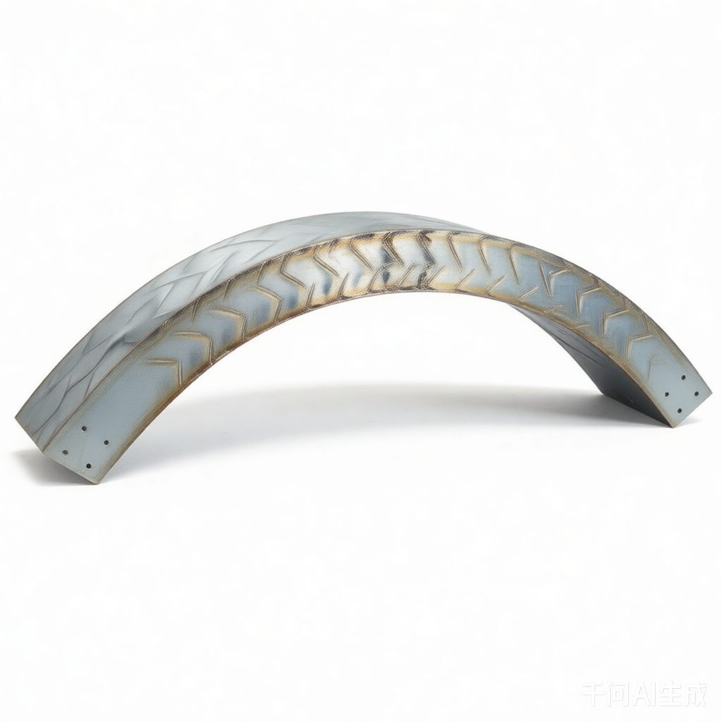
Aluminum Profile Bending
Press-Bend Welding of Aluminum Profiles - Frames and Corners
Bent and welded frames: ±1° before welding, ±1.5 mm after, plus an honest note on heat-affected zone strength at 50-65% of parent metal.
Product Details
Bending and welding are usually specified together because a frame needs both. They are also two processes that fight each other: bending produces a part with a springback that has to be compensated, and welding then adds heat that relaxes part of that compensation and shrinks the joint. A frame that is square when it comes off the bender is not square after the last weld.
We bend and weld structural frames in 6063-T5 and 6061-T6 with walls from 1.5 to 6 mm, using MIG and TIG, to an angular tolerance of ±1° before welding and a post-weld overall deviation of ≤±1.5 mm, in lengths up to 6,500 mm. This page is about the two things buyers most often get wrong: what a welded joint's strength actually is, and where the distortion comes from.
The joint is weaker than the weld
A specification that says "weld strength ≥85 percent of base metal" is a statement about the weld metal — the filler and the fused zone. It is not a statement about the joint, and on a heat-treatable alloy the joint is where the weakness is.
When 6061-T6 or 6063-T5 is welded, the heat-affected zone either side of the weld is heated above the aging temperature and the strengthening precipitates dissolve or coarsen. The result is a soft band, typically 5–25 mm wide, running along both sides of every weld.
| Region | Typical strength after welding | Notes |
|---|---|---|
| Weld metal (5183 / 5356 filler) | ~85–95% of base metal | The figure quoted in most specifications |
| Heat-affected zone, as welded | ~50–65% of base metal | The actual weak link |
| Heat-affected zone, after natural aging (30 days) | ~65–75% | Recovery is slow and partial |
| Heat-affected zone, after post-weld artificial aging | ~80–90% | Recovers strength but distorts the part; see below |
The practical consequence: if you design a frame using the parent metal's yield strength, the joint is at 60–70 percent of what you assumed. That is usually acceptable for a static frame with a generous safety factor, and it is not acceptable for a cyclically loaded member or a part sized to the limit.
There are four honest responses:
- Thicken at the joint. A local gusset or a thicker section at the connection moves the critical stress away from the soft band. This is the cheapest fix and it is done at design stage.
- Design the joint to a low-stress location. Put the weld where the bending moment is small — near a support rather than at mid-span.
- Post-weld artificial aging. Recovers most of the strength, and it also relaxes the welding residual stress. It distorts the part, so it has to be planned with a straightening step.
- Use a non-heat-treatable alloy. 5083 or 5754 welded joints retain a much higher fraction of parent strength because there is no precipitate to dissolve. The trade is lower extrudability and lower parent strength.
Where the distortion comes from
Every weld shrinks. Transverse shrinkage across a butt weld is typically around 1–2 mm per metre of weld, longitudinal shrinkage along the weld is roughly 0.5–1 mm per metre, and the two produce angular distortion when the weld is not symmetric about the neutral axis of the joint.
On a bent frame, the shrinkage does three things that matter:
It closes the bend angle. A 90° corner welded on the inside of the joint pulls closed by a fraction of a degree to a degree, depending on the weld size and the section. The bend was set to 90° plus springback compensation; after welding it is not 90°.
It pulls the frame out of square. On a rectangular frame with four corners, the shrinkage at each corner interacts, and the diagonals change. A frame that measured square before welding can be 2–3 mm out across the diagonals afterwards.
It bows the members. A weld along one side of a member shrinks that side more than the other, and the member bows toward the weld.
The standard controls, in order of effectiveness:
- Pre-set the angle. Bend the corner open by the amount the weld will close it. The amount is established from a trial joint on the same section and weld size, not from a table.
- Balance the weld. Weld symmetrically about the neutral axis where the joint allows it, so the shrinkage pulls both ways. A double-sided weld distorts far less than a single-sided one of the same total size.
- Sequence. Tack in a pattern that allows shrinkage to distribute, weld from the centre of long seams outward, and alternate sides. This is a planning decision made before the torch is lit.
- Fixture. Clamp the frame to a rigid fixture during welding and let it cool in the fixture. It controls distortion and it locks in residual stress, which then has to be considered.
- Machine after welding. Where the tolerance is tighter than the distortion, the answer is to weld with stock and machine the critical features afterwards. This is the most reliable route and it costs a machining step.
Specifications
| Item | Reference value |
|---|---|
| Process | Bending plus welding of structural assemblies |
| Wall thickness | 1.5–6 mm |
| Bend forms | L, U-channel, Z-frame, right-angle |
| Angle tolerance before welding | ±1° |
| Welding processes | MIG, TIG |
| Weld metal strength | ≥85% of base metal |
| Joint efficiency, as welded | Reference 50–65% in the heat-affected zone |
| Post-weld overall deviation | ≤±1.5 mm |
| Filler | Matched to base metal (5183 or 5356 for 6xxx) |
| Maximum length | 6,500 mm |
| Alloys | 6063-T5, 6061-T6 |
| Equipment | CNC press brakes, MIG/TIG welders, CNC machining centres |
| Surface treatment | Anodising, hard anodising, powder coating |
| Standard | GB/T 6892-2023, ISO 9001 |
MIG or TIG
| MIG | TIG | |
|---|---|---|
| Speed | Fast; suited to long seams | Slow; suited to short, precise joints |
| Heat input | Higher, more distortion | Lower and controllable, less distortion |
| Appearance | Good with practice; more spatter | Clean, uniform bead; better for visible joints |
| Thickness | Better above about 3 mm | Better on thin wall, 1.5–3 mm |
| Typical use | Long frame seams, structural members | Visible corners, thin wall, precise fit-ups |
The choice affects distortion as much as appearance. On a thin-wall visible frame, TIG at low heat input will hold the geometry better and need less post-weld correction, at a higher labour cost per metre. On a heavy structural frame with long seams, MIG is the practical choice and the distortion is managed by sequence and pre-set instead.
Where it does not fit
- The joint has to carry full parent-metal strength in a fatigue application. A welded 6xxx joint does not do that. Change the alloy, change the design so the weld is not in the load path, or use a mechanical connection.
- The tolerance is tighter than ±1.5 mm over a welded frame. Shrinkage will exceed it. Weld with stock and machine the critical features afterwards, or design the interface to float.
- The frame is thin-wall and visible. Welding thin wall distorts it, and the HAZ shows as a colour difference after anodising. Powder coating hides the colour shift; anodising does not.
- The part will be anodised after welding. The weld and the HAZ anodise differently from the parent metal, producing a visible band. This is a materials fact, not a process failure, and it is the reason welded visible frames are usually painted.
- The design assumes the weld is as strong as the extrusion. It is not, in the HAZ. Re-check the load case before production.
- You need a certified weld procedure and welder approval. We weld to a documented procedure and can supply the records; formal third-party qualification is a separate arrangement and affects the schedule.
What to send for a quote
Send the section drawings, the bend geometry, the assembly drawing with the weld symbols and locations, the alloy and temper, the load case for any structural member, the quantity, and the surface finish. Tell us which dimensions are critical after welding — that single piece of information decides whether the part is welded to size or welded with stock and machined.
We will reply with the weld sequence and pre-set we would use, the expected distortion and how it is controlled, the joint efficiency you should design to, and the tolerance we can confirm after welding. Where a drawing assumes parent-metal strength at a weld, that goes in the reply rather than in a test report.
FAQ
What tolerance can you hold after welding?
Reference ±1.5 mm overall on a welded frame, with ±1° on the bend angle before welding. Those are capability references and they are limited by shrinkage, not by machining. The value on your order is set by your drawing, and where a dimension is tighter than the distortion we will propose welding with stock and machining afterwards, and confirm that route in writing before you order.
What is the difference between press-bend welding and pure bending?
Pure bending delivers one formed part. Press-bend welding delivers an assembly: several bent segments joined into a frame or a structure. That adds a weld, a heat-affected zone, shrinkage and a post-weld dimensional requirement, so the acceptance criteria and the process planning are different.
Which welding process do you use?
MIG and TIG, chosen by thickness, joint access and appearance. TIG at low heat input for thin wall and visible corners; MIG for longer seams and heavier sections. The filler is matched to the base metal — 5183 or 5356 for 6xxx alloys.
Can post-weld dimensional accuracy be guaranteed?
To ±1.5 mm overall, yes, with a planned sequence and pre-set. Tighter than that, the honest answer is to weld with machining stock and cut the critical features afterwards. What cannot be guaranteed is a tight tolerance on a part that is welded to final size and never machined.
What inspections are done after welding?
Weld appearance and profile, dimensional check against the drawing, and where specified a dye penetrant or a visual check on the weld toe. For structural joints we can supply the weld procedure record and the filler certificates. If your project needs radiographic or ultrasonic inspection, tell us at enquiry — it is arranged separately.
How is it priced?
On the assembly complexity, the total weld length, the number of joints, the fixture and the finishing. Distortion control is real labour: a pre-set, a sequence and a fixture are all work. A price that ignores them is a price that will be renegotiated after the first lot comes out of square.
What is the minimum batch and lead time?
Reference minimum 50 kg, with small batches supported. A welded assembly needs a fixture, which is a setup cost on the first order and amortises afterwards. Lead time depends on the fixture, the welding and whether a post-weld machining step is involved.
Send your drawing
Email the section and assembly drawings, the weld locations, the alloy and the critical post-weld dimensions to linjunbing@truetrustlv.com, or send it on WhatsApp at +86 136 6644 0600. You will get a weld sequence, a distortion estimate and a written tolerance statement.
GET A QUOTE
Once you have submitted your requirements, we will contact you as soon as possible regarding your product inquiry.:Press-Bend Welding of Aluminum Profiles - Frames and Corners