
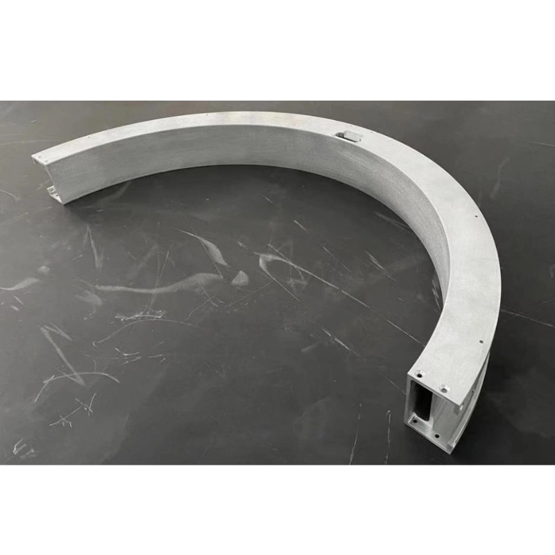
Aluminum Profile Bending
Thick Wall Aluminum Bending - 8 to 12 mm Heavy Load
Heavy-wall bending in 6061-T6 and 6082-T6: outer fibre strain calculation, springback compensation, neutral axis shift, radius ≥5x wall.
Product Details
Thick-wall bending fails for the opposite reason to thin-wall bending. A 1 mm wall cracks because there is not enough material to distribute the strain; an 8 mm wall cracks because the strain on the outside of the bend is arithmetically too large. It is a calculation, not a judgement, and it can be done before the part is ordered.
We bend sections with 8–12 mm walls in 6061-T6 and 6082-T6, as thick right-angle bends, heavy U-channels and load-bearing Z-frames, with an angular tolerance of ±1° in lengths up to 6,500 mm. Here is what governs that work.
The strain calculation that decides feasibility
When a profile bends, the material at the outside of the curve has to stretch. The engineering strain on the outer fibre is:
ε = t / (2R + t)
where t is the wall thickness and R is the inside bend radius. This is the single most useful formula in bending, because it converts a drawing into a feasibility answer.
| Wall | Inside radius | R/t | Outer fibre strain | Verdict for 6061-T6 |
|---|---|---|---|---|
| 8 mm | 8 mm | 1.0 | 33% | Will crack; not achievable |
| 8 mm | 16 mm | 2.0 | 20% | Will crack |
| 8 mm | 32 mm | 4.0 | 11% | Marginal; near the elongation limit |
| 8 mm | 40 mm | 5.0 | 9% | Workable with a good die and a clean surface |
| 12 mm | 48 mm | 4.0 | 11% | Marginal |
| 12 mm | 60 mm | 5.0 | 9% | Workable |
6061-T6 has an elongation at break of roughly 10–12 percent, and the usable forming strain is lower than the tensile figure because a bend concentrates strain on one surface. So a rule of thumb for T6 thick-wall work: keep the outer fibre strain at or below about 9 percent, which means an inside radius of at least 5 times the wall thickness.
For T5 tempers, which have more ductility, 3–4 times the wall is often workable. That difference is the reason a design that bends in 6063-T5 cracks in 6061-T6 at the same radius, and it is arithmetic rather than opinion.
Springback: large in absolute terms, and it does not scale down
Thick-wall springback is bigger than thin-wall springback in absolute angle, for a reason that is easy to miss: a thick section has a larger elastic core. When the bending load is released, that core recovers elastically and pulls the bend open.
Three practical consequences:
Compensation is mandatory and it is not a small number. On a heavy section the recovery can approach several degrees, which is many times the ±1° tolerance. The die has to be set well past the target, and the amount is established by pressing a test piece.
The compensation is section-specific, not material-specific. Two heavy sections of the same alloy need different compensation because the elastic core differs. That is why a shop keeps records per section, and why the first order of a new section takes longer than the tenth.
Batch variation is amplified. A small difference in yield strength produces a small difference in springback on a thin section and a larger one on a thick section, because the elastic energy stored is larger. A setting that works on one heat may need adjustment on the next.
Neutral axis shift: why your blank length is wrong
The developed length of a bent part is calculated on the neutral axis, the layer that neither stretches nor shortens. For thin walls, that layer is close to the mid-thickness and the standard assumption of 0.5t works well.
For thick walls at a tight radius, the neutral layer moves toward the inside of the bend, because the outer material stretches more than the inner material compresses. The shift increases as the radius-to-thickness ratio falls. If you calculate the blank length assuming 0.5t on an 8 mm wall bent to R = 4t, you will be short by a millimetre or more on each bend, and two bends compound the error.
The practical fix is to use a K-factor from a bend table for the actual R/t, or better, from a trial bend of the actual section. On heavy load-bearing frames where the ends have to meet, that correction is the difference between a part that assembles and one that is scrapped after machining.
Specifications
| Item | Reference value |
|---|---|
| Wall thickness | 8–12 mm (heavier by arrangement) |
| Bending types | Thick right-angle, heavy U-channel, load-bearing Z-frame |
| Angular tolerance | ±1° with springback compensation |
| Minimum inside radius | ≥5× wall for T6; ≥3–4× wall for T5 |
| Maximum length | 6,500 mm |
| Alloys | 6061-T6, 6082-T6 |
| Equipment | Large-tonnage CNC bending machines, CNC machining centres |
| Downstream | CNC milling, drilling, tapping, cutting, welding |
| Surface treatment | Anodising, hard anodising, powder coating |
| Standard | GB/T 6892-2023, ISO 9001 |
Thick wall against thin wall
| Thin wall, 1–3 mm | Thick wall, 8–12 mm | |
|---|---|---|
| Tonnage | Small to medium machine | Large-tonnage CNC machine |
| Springback | Small, easy to control | Large; needs measured compensation |
| Angle accuracy | ±0.5–1° | ±1° with compensation |
| Tooling | Conventional | Heavier die; polished contact faces |
| Surface indentation | Slight | Needs die polishing control at high contact stress |
| Dominant failure | Wrinkling, then cracking | Outer fibre cracking by strain, or tool marking |
| Typical alloys | 6063-T5 | 6061-T6, 6082-T6 |
The sixth row is the important reversal. On thin walls the crack is a wrinkling consequence: the inside buckles, then the outside tears as the geometry collapses. On thick walls there is no wrinkling — the material is too stiff — so the crack is purely a strain limit on the outside. That is why the thin-wall fix is support, and the thick-wall fix is radius.
Die marking, and why it matters more than it looks
Thick-wall bending needs high contact stress. High contact stress means the die leaves marks, and on a load-bearing part a mark is not cosmetic: it is a stress concentration and, on a part that will see fatigue, a crack initiation site.
The controls are die surface preparation and lubrication. Contact faces are polished, and the polish is maintained — a polished die stops being polished after a few hundred heavy cycles, and the marks come back gradually, so the deterioration is not noticed until parts start failing inspection.
There is also a limit to how much the die can be polished. On a very heavy section, the contact stress can exceed what any die surface will survive without marking, and the answer is a larger die radius or a machined relief, not more polishing.
Where it does not fit
- The inside radius is below about 5 times the wall in T6. Outer fibre strain exceeds the material's elongation and the part cracks. Run the ε = t/(2R+t) calculation before ordering, not after.
- You need ±0.5° on a heavy section. Springback at this thickness is large and varies with the batch. Accept ±1°, or move the accuracy requirement to a machined feature.
- The part is a visible architectural component. High contact stress marks the surface, and a heavy polished section shows every mark. A fabricated or a cast part may be better for appearance.
- The section is thick and hollow with a small cavity. The mandrel or filler cannot be inserted and withdrawn, and the cavity collapses. A solid or an open section is easier.
- The tonnage exceeds the machine at the requested radius. Increase the radius, reduce the section, or split the part. Trying harder is not an option.
- The part must be anodised and the bend is visible. Thick-wall bending produces flow lines that show after anodising. Consider painting or a machined finish.
What to send for a quote
Send the section drawing with the wall thickness, the bend drawing with the inside radius and angle, the alloy and temper, the length and the quantity. Tell us the load the part carries and the direction, because a thick section is usually doing structural work and the bend is often the weak point in the load path.
We will reply with the outer fibre strain at your radius, whether it is inside the material's forming limit, the springback compensation we expect, the tooling we would use, and the tolerance we can confirm. If the radius is below the strain limit, that goes in the reply before anything is cut.
FAQ
What tolerance can you hold on a heavy bend?
Reference ±1° on angle with measured springback compensation, over lengths up to 6,500 mm. That is a capability reference for an 8–12 mm wall in T6, where the elastic core is large and the recovery varies with the batch. The value on your order is set by your drawing, and we confirm in writing what we can hold on your angle and your inside radius before you order — including when the radius is below the strain limit and we cannot hold it at all.
What is the difference between thick-wall and thin-wall bending?
The failure mechanism. Thin-wall bending fails by wrinkling on the inside and then cracking, and it is solved with internal support. Thick-wall bending does not wrinkle because the material is too stiff; it fails by outer fibre strain exceeding the ductility, and it is solved with a larger radius. The equipment, the tonnage and the springback are all different too.
How is the springback problem solved?
By measuring it and compensating for it. The die is set past the target angle, and the amount of over-bend is established on a test piece of the actual section and alloy. On heavy sections the recovery can be several degrees, so compensation is not optional. The compensation value is recorded per section, because the elastic core differs between sections even of the same alloy.
What is the minimum bend radius for a thick wall?
It follows from the strain limit. Use ε = t/(2R + t) and keep it at or below about 9 percent for T6, which gives an inside radius of at least 5 times the wall thickness. For T5 tempers, 3–4 times the wall is often workable. We calculate this for your section before quoting rather than giving a generic ratio.
6061-T6 or 6082-T6?
6061-T6 for general high-strength structural work: widely available, well understood, good machining. 6082-T6 for heavier load with better toughness, which matters on a part that sees impact or fatigue. Both are formable only within the strain limit, and 6082 is not a licence to use a tighter radius.
Why is my blank length wrong?
Because the neutral axis shifts toward the inside of the bend at small R/t, and a calculation assuming 0.5t gives a blank that is too long. Use a K-factor from a bend table for the actual R/t, or from a trial bend of the section. On two-bend parts the error compounds.
What is the minimum batch and lead time?
Reference minimum 50 kg. Thick-wall work needs a test press to establish springback, so the first order of a new section carries a setup that later orders do not. We quote the two cases honestly rather than averaging them into one number.
Send your drawing
Email the section drawing, the bend geometry with the inside radius, the alloy and the load case to linjunbing@truetrustlv.com, or send it on WhatsApp at +86 136 6644 0600. You will get the outer fibre strain at your radius, a feasibility verdict and a written tolerance statement.
GET A QUOTE
Once you have submitted your requirements, we will contact you as soon as possible regarding your product inquiry.:Thick Wall Aluminum Bending - 8 to 12 mm Heavy Load