
Aluminum Profile Bending
Complex Cross-Section Aluminum Bending - Multi-Cavity Profiles
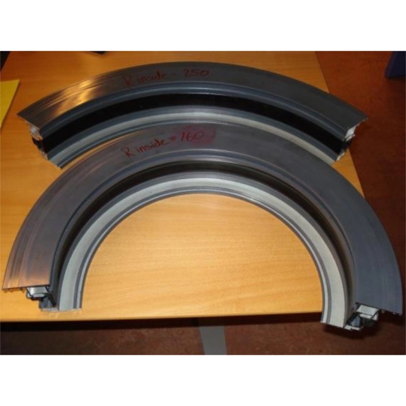
Bending multi-cavity, asymmetric and grooved profiles: shear centre offset causes twist, dedicated dies, cavity support, ±0.4 mm radius.
Product Details
An ordinary profile bends predictably: the force is roughly even, the section keeps its shape, and the problem is springback. A complex section does not behave that way. Multi-cavity, asymmetric, grooved or hollowed profiles concentrate stress in places the drawing does not mark, and the part fails in a mode that is not on the tolerance list — collapse, corner cracking, or a twist that appears only after the part is released.
We bend multi-cavity, irregular, asymmetric and hollowed profiles in 6063-T5, 6061-T6 and 6082-T6, with a reference radius error of ±0.4 mm, angular tolerance ±1° and flatness 0.1–0.5 mm. Here is what makes these parts different.
Why the stress is not even
On a symmetric solid or simple open section, the bending force distributes across the section in a predictable way, and the neutral axis sits where the geometry says it should. On a complex section, three things break that assumption.
The shear centre is not the centroid. On an asymmetric section — one with a groove on one side, or a cavity offset from the middle — the point about which the section twists is not the same as the point where the load is applied. Bending load applied at the geometric centre therefore produces a twisting moment as well as a bending moment. The part comes out curved and twisted, and the twist is not a springback artefact: it is in the loading.
The wall thickness is not uniform. Thick regions resist bending, thin regions yield first. The neutral axis shifts toward the thick side, and the thin wall carries more strain than its share. That is where the crack starts.
Cavities collapse locally. A hollow cavity with no internal support flattens at the bend, and the flattening is local — it happens at the point of maximum curvature, not uniformly along the length. A multi-cavity profile can have one cavity collapse while the others stay round, which makes the distortion hard to see and hard to correct.
Twist: the failure that is not on the drawing
Twist is the characteristic failure of asymmetric bending, and it deserves its own explanation because it is routinely mistaken for a machine problem.
When a section is bent, the material on the inside of the curve shortens and the material outside stretches. If the section is symmetric, the two effects balance and the section stays in its plane. If it is asymmetric, the shortening and stretching do not balance about the load line, and the section rotates as it bends.
Once rotated, the effective bending stiffness changes, because the section is now being bent about a different axis. So the part twists progressively along the arc — a little at the start, more in the middle — and the finished part is a helix rather than an arc.
The fixes are limited:
- Support the section so it cannot rotate. A dedicated die with a close-fitting cavity prevents the rotation, at the cost of a die per section.
- Load through the shear centre rather than the geometric centre. This is a tooling change and it requires knowing where the shear centre is, which means a section analysis, not a guess.
- Symmetrise the section. If the design allows, adding a balancing rib or moving the groove to the centre removes the problem at the source. It is a die change and it is usually the cheapest long-term answer.
Support: what a multi-cavity section needs
A complex section cannot be bent with a generic die and hope. It needs a die shaped to the section, and it usually needs internal support in every cavity that will collapse.
| Support method | Where it applies | Limitation |
|---|---|---|
| Close-fitting bending die | All complex sections | One die per section; die cost is the main setup cost |
| Multiple mandrels | Multi-cavity hollow sections | Each cavity needs access to withdraw the mandrel |
| Elastomer insert | Closed cavities, moderate radii | Compresses at tight radii and stops supporting |
| Low-melting filler | Tight radii, complex interiors | Adds a melt-out step per part |
| Pressure pad on flanges | Open sections with flanges | Only supports the flange, not the web |
The choice is driven by whether the cavity can be reached. A through-cavity can take a mandrel; a blind or curved cavity cannot, and needs a filler. That is a feasibility question, and it is answered from the section drawing before any tooling is committed.
Specifications
| Item | Reference value |
|---|---|
| Applicable sections | Multi-cavity, irregular, asymmetric, grooved, hollowed |
| Bending forms | Complex arc, irregular bend, compound bend |
| Radius error | ±0.4 mm |
| Angular tolerance | ±1° |
| Flatness | 0.1–0.5 mm |
| Maximum length | up to 20 m |
| Alloys | 6063-T5, 6061-T6, 6082-T6 |
| Equipment | Precision CNC press brakes, dedicated bending dies, CNC machining centres |
| In-house support | Die design, extrusion, CNC machining, precision slot milling |
| Surface treatment | Anodising, hard anodising, powder coating |
| Standard | GB/T 6892-2023, ISO 9001 |
Complex section against ordinary section
| Ordinary profile | Complex section | |
|---|---|---|
| Geometry | Solid or simple symmetric | Multi-cavity, irregular, asymmetric, grooved |
| Stress state | Even, wide process window | Uneven, with local concentration |
| Typical defects | Springback, angle deviation | Section collapse, corner cracking, twist |
| Tooling | General-purpose bending die | Dedicated die, plus internal support |
| Difficulty | Conventional | High; feasibility must be checked first |
Inspection: radius is not enough
On a complex part, checking the radius tells you almost nothing about whether it will assemble. The dimensions that fail are the ones that are not measured by default:
Section distortion. The cavity is no longer round, the slot is no longer parallel, the flange is no longer flat. The check is a section gauge or a 3D scan of a cut sample, compared with the nominal section.
Twist. Measured as the angular deviation of a datum face at intervals along the arc. A part can be perfectly curved and still be a helix.
Wall thinning on the outer fibre. The outer wall stretches, and the thickness reduction is a strength reduction. On a load-bearing bracket this matters more than the radius.
Corner cracking. Often a hairline, often invisible until anodising, when the crack wicks and shows as a dark line. On a part that will be anodised, ask for a crack check before the coating goes on, not after.
Where it does not fit
- The section is strongly asymmetric and thin-walled. Twist and collapse combine and neither can be fully controlled. Symmetrise the section or accept a machined part.
- The cavities cannot be reached for support. Without internal support, a hollow cavity collapses at the bend. A filler can solve it, at a cost per part.
- The radius is below about 2.5 times the section depth. Distortion becomes the dominant effect and the section will not hold its shape. A larger radius, a softer temper, or a welded corner is the answer.
- You need one part for a prototype. A dedicated bending die is not economical for one piece. Machine the shape from solid or use a different construction.
- The part has to be anodised and the outer corner is Class A visible. Cracking and stretch marks both risk showing. If the appearance is critical, plan a post-forming machining or a paint finish.
- Your drawing gives only a radius and an angle. Without a definition of the datum faces and an allowance for section distortion, the acceptance criteria are ambiguous. That gap has to be closed before production, not at first article.
What to send for a quote
Send the section drawing with wall thicknesses and cavity positions marked, the bend drawing with radius and arc, the alloy and temper, the quantity, and which faces are functional (guide faces, sealing faces, visible faces). If the part carries load, tell us the load direction — an asymmetric section bent about one axis behaves very differently from the same section bent about another.
We will reply with a feasibility assessment: whether the section can be supported, the twist risk, the die we would need, and the tolerances we can confirm on the radius and on the section distortion. Where the section cannot be bent to the drawing, that goes in the reply before tooling is committed.
FAQ
What makes a section "complex" for bending?
More than one cavity, an asymmetric layout, a groove or a deep slot, a large variation in wall thickness, or any combination. The common factor is that the stress is not evenly distributed during bending, so the failure modes are distortion and cracking rather than simple springback.
Why does my part come out twisted?
Because the section is asymmetric. The shear centre and the geometric centre are in different places, so a load applied at the geometric centre creates a twisting moment. The part rotates as it bends, and the rotation changes the effective bending axis, so the twist grows along the arc. The fix is support that prevents rotation, or a more symmetric section.
What tolerance can you hold?
Reference radius error ±0.4 mm, angular tolerance ±1°, flatness 0.1–0.5 mm. These are capability references. The value on your order is set by your drawing, and on a complex section we also need to agree the section distortion acceptance, because the radius can be in tolerance while the cavity is not. We confirm both in writing before you order.
Can a multi-cavity section be bent at all?
Yes, with support in each cavity and a dedicated die. The limit is whether the cavities can be reached for support: a through-cavity can take a mandrel, a blind cavity needs a melt-out filler. If neither is possible, the cavity will collapse.
Which alloy should I choose?
6063-T5 for formability: it has the most ductility and the lowest springback, which matters most on an asymmetric section. 6061-T6 where strength is required, with a larger minimum radius and more distortion. 6082-T6 as a middle option for loaded parts.
Can it be anodised after bending?
Yes, and that is the right sequence. Anodising before bending cracks the coating on the outer fibre, and on a complex section the crack is likely to be at a corner where it will wick and show. Where the part is welded as well, the order is bend, weld, machine, anodise.
How is it priced?
On the section complexity, the die, the radius and the quantity. A dedicated bending die is the dominant setup cost on a complex section, which is why the first order and the tenth order are priced very differently per part. We quote the die separately so the amortisation is visible.
Send your drawing
Email the section drawing, the bend geometry, the alloy, the load direction and the functional faces to linjunbing@truetrustlv.com, or send it on WhatsApp at +86 136 6644 0600. You will get a feasibility assessment, a distortion risk note and a written tolerance statement.
GET A QUOTE
Once you have submitted your requirements, we will contact you as soon as possible regarding your product inquiry.:Complex Cross-Section Aluminum Bending - Multi-Cavity Profiles