
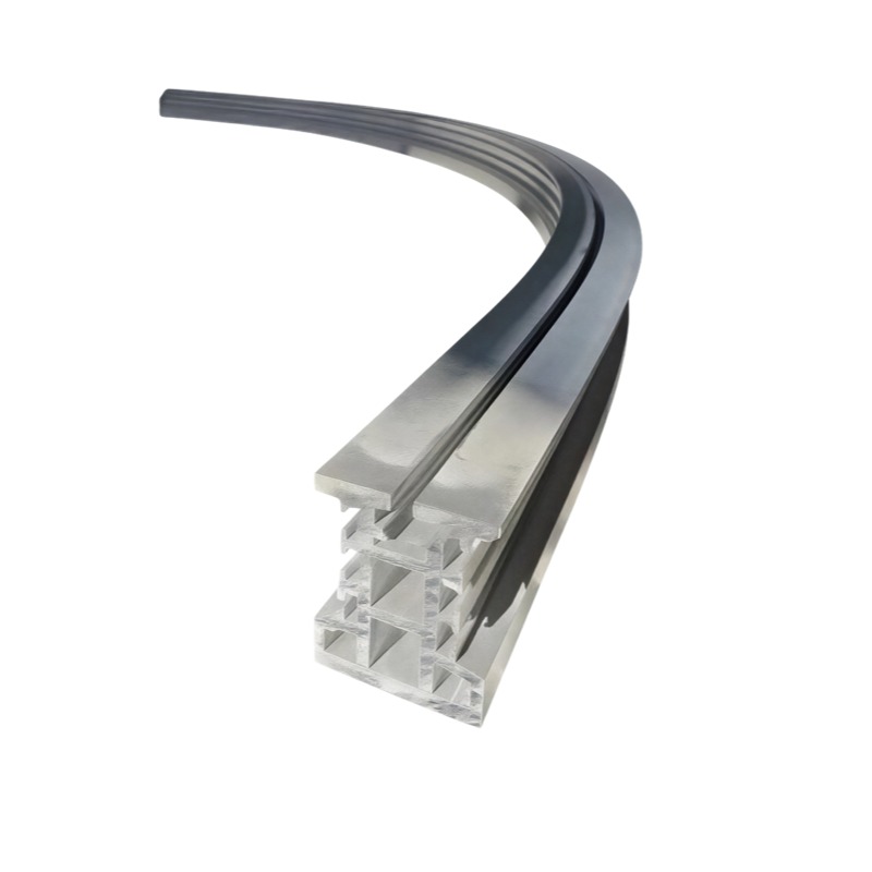
Aluminum Profile Bending
Rail Bending - RGV AGV Curved Guide Rails
Bent guide rails for RGV/AGV and stacker cranes: radius ±0.4 mm, splice gap ≤0.5 mm, mitred joints, slot closure controlled, anodised after bending.
Product Details
A bent rail has one job: a wheel or roller has to run along it without binding, jumping or wearing unevenly. Every tolerance on the drawing is a proxy for that, and some of the proxies are better than others. A rail can be 0.4 mm inside its radius tolerance and still make a carriage jump at every joint, because the failure that matters is continuity, not accuracy.
We bend RGV and AGV track profiles, annular guide rails and stacker crane rail arcs in 6063-T5, 6061-T6 and 6005A-T6, with a reference radius error of ±0.4 mm and a splice gap of ≤0.5 mm. This page is about what those numbers protect and what they miss.
The running surface is the functional surface
Most bent parts are judged on their outside dimensions. A rail is judged on its guide surfaces — the faces the wheel touches. Those faces have to stay in the right relationship to each other after bending, and bending is exactly the operation that tries to change that relationship.
When a rail profile is bent, the outer wall stretches and thins, the inner wall compresses and thickens, and any hollow or channel section tends to close up at the bend. For a guide rail, that "closing up" means the guide slot gets narrower at the bend, and the roller that fitted with clearance on the straight section now runs tight.
The failure mode is not a dimension out of tolerance. It is a carriage that runs smoothly on the straight and binds on the curve, with no measurement on the drawing explaining why.
Three things bending does to a rail
The slot narrows. A channel or a slotted profile closes slightly at the bend because the inner flange compresses. The amount depends on the radius relative to the section depth: a tight radius on a deep section closes more. The fix is to form the slot oversize, or to support the profile from inside during bending, or to machine the slot after bending.
The section twists. An asymmetric rail — one with the guidance feature on one side — twists along the arc, because the mass and the stiffness are not symmetric about the neutral axis. A twisted rail sits on its supports with the guide face at a varying angle, so the roller is loaded on one edge and wears a chamfer into the wheel.
The running face loses flatness. The reference 0.1–0.5 mm flatness figure is what keeps the roller in full contact. A wavy running face produces a varying contact stress, which shows up as noise and as uneven wheel wear before it shows up as a dimensional failure.
Continuity matters more than absolute accuracy
This is the point worth taking away. A roller following a curve can tolerate a gradual error: if the radius is 0.4 mm out over the whole arc, the carriage follows a slightly different curve and no one notices. What it cannot tolerate is a sudden change — a step at a joint, or a flat spot where two bends meet.
| Condition | What the roller does | Severity |
|---|---|---|
| Radius 0.4 mm out, uniform | Follows the curve; slight lateral offset, no impact | Low |
| Radius drifting gradually along the arc | Side load builds up; guide wears on one side | Medium |
| Radius correct on each segment, tangent mismatch at the joint | Impact at every pass; noise, wheel flat, bolt loosening | High |
| Flat spot in the middle of a curve | Local impact, high contact stress | High |
| Twist varying along the arc | Edge loading, uneven wear, vibration | High |
So the specification that matters for a segmented rail is not the radius tolerance on each segment. It is the tangent continuity at the joint, which is a different number and is usually not on the drawing at all.
Splice gaps: why 0.5 mm is the number
A 0.5 mm gap is small enough that a wheel of normal hardness will roll over it rather than drop into it, provided the gap is also chamfered or the joint is mitred. An unlanced butt joint with a sharp edge produces an impact at every pass even at 0.5 mm.
Three joint treatments, in order of how well they work:
Mitred joint. The two ends are cut at an angle so the gap is presented diagonally to the wheel rather than square to it. The wheel rolls across a diagonal gap instead of dropping into a square one. This is the best treatment for a running surface and it needs a cut-to-length accuracy that a straight saw cut does not give.
Chamfered butt joint. The edges are broken so the wheel rides over a ramp rather than a step. Simpler than a mitre and nearly as effective at small gaps.
Straight butt joint. Acceptable where the wheel is large relative to the gap or the carriage moves slowly. Not acceptable at speed.
There is also the alignment question: a joint that is flush on the running face but stepped laterally will guide the wheel sideways at every pass. The joint has to be controlled in three directions, not one.
Specifications
| Item | Reference value |
|---|---|
| Bending forms | Rail bending, bent rail, arc guide rail |
| Applications | RGV/AGV track, annular guide rail, stacker crane rail arc |
| Bending radius error | ±0.4 mm |
| Curvature accuracy | ≤0.5° |
| Flatness | 0.1–0.5 mm |
| Splice gap | ≤0.5 mm |
| Maximum length | up to 20 m |
| Alloys | 6063-T5, 6061-T6, 6005A-T6 |
| In-house support | Profile die design, extrusion, CNC machining |
| Surface treatment | Anodising, hard anodising |
| Standard | GB/T 6892-2023, ISO 9001 |
| Minimum batch | 50 kg |
Rail bending versus bending a structural profile
| Structural profile bending | Rail bending | |
|---|---|---|
| Accuracy basis | General angle control | Radius error ±0.4 mm, curvature ≤0.5° |
| Splicing | Rarely critical | Splice gap ≤0.5 mm, tangent continuity required |
| Surface | General | No scratches or wrinkles on the running face |
| Function | Static structure | Dynamic path for a moving carriage |
| What fails first | Radius out of tolerance | Joint impact, slot narrowing, twist |
The last row is the useful one. On a structural part, the inspector measures the radius and signs it off. On a rail, the inspector measures the radius, signs it off, and the carriage still binds — because the problem is in the slot or at the joint, neither of which appears on a radius check.
Where it does not fit
- The radius is below about 3 times the section depth. The section closes and the slot narrows beyond what a roller will accept. Use a larger radius, a shallower section, or machine the slot after bending.
- The rail is a closed hollow section with no internal support access. It will collapse at the bend unless a filler can be introduced and removed. If not, the section is not bendable at that radius.
- You need a tight tolerance on the slot width after bending in 6061-T6. T6 bends with more springback and more section distortion. Bend in T5 and age, or machine the slot afterwards.
- The assembly cannot tolerate a joint. Then it has to be one piece, and one piece is limited by the 20 m length and by transport. A joint at a tangent point, away from the highest-speed section, is usually better than fighting for a single piece.
- The rail has to be anodised before installation and the running face must stay unworn. Anodising gives a hard but brittle layer; a roller running on it will wear through at the contact line. Hard anodising helps, and it still wears. Consider a hardened insert or a different rail design for high-cycle duty.
- You need a certified dynamic test of the completed track. We deliver the geometry. The carriage dynamics, the noise and the wear test belong to the track builder and the integrator.
What to send for a quote
Send the rail section drawing with the guide faces marked, the bend geometry with radius and arc length, the number of segments if the track is segmented, the alloy, the wheel or roller diameter and load, and the surface treatment. The roller data matters more than it looks: a 50 mm roller and a 150 mm roller have very different tolerance for a joint gap.
We will reply with the achievable radius for your section, the anticipated slot closure, the joint treatment we recommend, and the tolerances we can confirm — including the tangent continuity at joints if the track is segmented. Where a radius will close the slot beyond acceptance, that goes in the reply.
FAQ
What is different about bending a rail rather than a structural profile?
The functional surface. A structural part is judged on its outside dimensions; a rail is judged on whether a roller runs along it smoothly. That means slot width after bending, twist along the arc, flatness of the running face and tangent continuity at joints all matter, and the last three are usually not on the drawing.
What accuracy can you hold?
Reference: radius error ±0.4 mm, curvature ≤0.5°, flatness 0.1–0.5 mm, splice gap ≤0.5 mm. These are capability references. The value on your order is set by your drawing, and for a segmented track we also need the tangent continuity requirement, because each segment can be in tolerance and the joint can still be wrong.
Does bending narrow the guide slot?
Yes, slightly, because the inner flange compresses at the bend. The amount grows as the radius gets tighter relative to the section depth. We allow for it in forming or machine the slot after bending, depending on the tolerance. If your slot tolerance is tight, tell us at enquiry — it changes the process, not just the price.
How should segments be joined?
Mitred where the joint is on a running surface, so the wheel crosses a diagonal gap instead of a square one. Chamfered butt joints are an acceptable second choice. A straight square butt joint at a small gap is workable at low speed and large wheels, and produces an impact at every pass otherwise. The joint also has to be aligned in three directions, not just flush on top.
Which alloy should I choose?
6063-T5 for most track: it bends well, holds a good surface, and distorts less. 6061-T6 where the rail carries structural load or needs higher strength, accepting more springback and more section distortion. 6005A-T6 for heavy duty and vibration, with better fatigue behaviour and reasonable formability.
Can the rail be anodised after bending?
Yes, and it should be. Anodising before bending cracks the coating on the outer fibre, which on a running surface is where the roller contacts. Bend, machine the joints and the mounting holes, then anodise. If the assembly is welded, weld before anodising as well.
What wheel size does the joint gap suit?
As a rule, a 0.5 mm gap is smooth for a roller of 40 mm diameter and above at moderate speed, and marginal below that. Send the roller diameter and the carriage speed and we will tell you whether to mitre the joint, chamfer it, or reduce the gap further.
Send your drawing
Email the rail section drawing with the guide faces marked, the bend geometry, the roller data and the joint requirement to linjunbing@truetrustlv.com, or send it on WhatsApp at +86 136 6644 0600. You will get the achievable radius, the expected slot closure and a joint recommendation.
GET A QUOTE
Once you have submitted your requirements, we will contact you as soon as possible regarding your product inquiry.:Rail Bending - RGV AGV Curved Guide Rails