
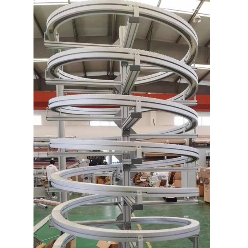
Aluminum Profile Bending
Spiral Roll Bending - 3D Helix Aluminum Profiles
Three-dimensional spiral bending with controlled pitch: full-circle error ±0.4 mm, up to 20 m, round tube, square tube, channel and angle.
Product Details
A spiral is not a bent circle. It is a circle that also moves along its axis while it is being formed, and that single extra motion is what makes it a different process with a different set of failure modes. The part that comes off the machine can have a perfect diameter, a perfect pitch and still not fit, because the two were formed independently and drifted apart.
We spiral roll bend round tube, square tube, channel, angle and special profiles in 6063-T5, 6061-T6 and 6082-T6, to a reference full-circle error of ±0.4 mm, in lengths up to 20 m. Here is what decides whether the result is usable.
The geometry, and the number that catches people
A spiral is defined by three parameters: the diameter, the pitch (the axial rise per turn), and the number of turns. The developed length of the profile is not the circumference times the number of turns — it is longer, because the profile travels both around and along.
The relationship is Pythagoras applied to one turn: the developed length per turn is the square root of the circumference squared plus the pitch squared. Over n turns, the total developed length follows the same form. For a large diameter and a small pitch the difference from the plain circumference is negligible; for a small diameter and a large pitch it is not.
This matters at the quotation stage, because the cut length determines the material order. A spiral quoted on circumference alone arrives short, and the last turn cannot be completed. The error is easy to make and expensive to discover after the profile has been extruded.
Two motions that have to stay in step
Spiral roll bending combines a rotational forming motion with an axial feed. The diameter comes from the roll setting; the pitch comes from the feed rate relative to the rotation. If either drifts, the spiral is wrong in a way that is not visible until the part is measured in three dimensions.
| What drifts | What you see | Why it happens |
|---|---|---|
| Axial feed rate | Pitch too large or too small, uniform along the part | Feed setting, or material slipping in the rolls |
| Roll pressure | Diameter drifts along the length; the spiral tightens or opens | Material hardness variation, or thermal growth in the machine |
| Section twist | Pitch varies; the profile rotates as it advances | Asymmetric section, uneven roll contact |
| Both motions together | Diameter correct and pitch correct, but the axis is not straight | Guide misalignment; the spiral is a cone or a banana |
The third row is the one that surprises people. A profile that twists as it is fed does not just look wrong — it changes the effective pitch, because a rotated section presents a different profile to the rolls. On an asymmetric section, twist and pitch are coupled, and you cannot correct one without affecting the other.
Roundness and pitch: two tolerances that interact
Drawings usually give the diameter tolerance and the pitch tolerance separately, as if they were independent. In spiral forming they are not, because the same roll pressure controls both the diameter and the grip that drives the feed.
Increase the roll pressure to hold the diameter and the material grips better, so the feed becomes more consistent — but the section distorts more. Decrease it and the section stays cleaner, but the feed slips and the pitch wanders. The working window is the range where both are acceptable, and on a thin or asymmetric section that window is narrow.
The reference figures reflect this: ±0.4 mm on the full circle, 0.1–0.5 mm on flatness. The flatness figure is the one that carries the pitch information for a multi-turn part — a spiral that is not flat in the axial direction has a pitch problem even if every diameter measurement is in tolerance.
Joints on a multi-turn spiral
A spiral longer than the available stock, or one that has to be installed in sections, needs a joint. This is where most of the practical difficulty sits, and it is worth understanding why.
A joint on a straight rail is a butt joint: two ends meet, the gap is controlled, done. A joint on a spiral has to preserve three things at once: the diameter, the pitch, and the angular position. If the joint is rotated slightly, the two halves are still each correct but the spiral has a step at the joint that the following turn inherits.
So a spiral joint needs:
- A controlled gap, on both the diameter and the pitch direction.
- An alignment feature — a machined face, a sleeve, or a pin — that fixes the angular position, not just the axial position.
- A joint design that survives handling, because a spiral is a spring and will try to open or close while it is being moved.
Where the application allows, a welded joint with a machined sleeve inside is the most robust: the sleeve carries the alignment and the weld carries the load. Where welding is not acceptable — an anodised visible part, or a profile that cannot take the heat — a mechanical joint with a machined keyway is the alternative, and it costs more.
Specifications
| Item | Reference value |
|---|---|
| Forms | Spiral bend, three-dimensional ring bend, multi-turn spiral |
| Geometry | Horizontal ring plus axial rise |
| Spiral types | Single turn, multi-turn continuous, spring-like winding |
| Full-circle error | ±0.4 mm |
| Flatness | 0.1–0.5 mm |
| Alloys | 6063-T5, 6061-T6, 6082-T6 |
| Sections | Round tube, square tube, channel, angle, special profile |
| Maximum length | up to 20 m |
| Equipment | Roll bending machines, spiral forming machines, CNC bending machines |
| In-house support | Die design, extrusion, CNC machining, welding |
| Surface treatment | Anodising, hard anodising, coating |
| Standard | GB/T 6892-2023, ISO 9001 |
| Minimum batch | 50 kg |
Where spiral forms are used
| Application | Why a spiral | What the profile must tolerate |
|---|---|---|
| Spiral conveyor | Continuous vertical transport in a small footprint | Sustained torsional load; section must resist twist |
| Vertical storage and retrieval guide | Continuous path between levels | Accurate pitch, so the carriage does not bind |
| Spiral staircase structure | Structural spiral stringer or handrail | Load plus appearance; welding and finishing after forming |
| Architectural helix | Visible decorative or functional helix | Surface quality; forming marks are not acceptable |
| Cooling or heating coil | Long path in a compact volume | Uniform pitch; a varying pitch changes the thermal profile |
| Spring-like flexible guide | Compliant path between fixed points | Controlled stiffness; the pitch is part of the spring rate |
Alloy choice, and where it bites
6063-T5 is the default. It forms well, holds a good surface, and has enough ductility to take the combined bend and feed without cracking. Most spiral conveyor and architectural work is in this alloy.
6061-T6 gives about 310 MPa and is used where the spiral carries structural load. It forms less easily: the ductility is largely consumed by the temper, so the minimum radius for a given section is larger than in 6063-T5, and the springback is higher, which makes the pitch harder to hold.
6082-T6 sits between them for strength with somewhat better forming behaviour than 6061, and it is a reasonable choice for a loaded spiral that still has to be formed.
Two things to be clear about. First, a stronger alloy does not make a spiral stiffer — Young's modulus is the same across all of them, so the spring rate of a spiral depends on the section geometry and the number of turns, not on the temper. Second, T6 tempers form worse than T5 in every case, so if the design is formability-limited, the alloy answer is to go softer and add section, not harder.
Where it does not fit
- The pitch is small relative to the diameter and the section is stiff. The axial feed has to overcome the section's resistance to being displaced sideways, and a stiff section will not follow a tight pitch. The result is a spiral with a pitch that varies around each turn.
- The section is asymmetric and thin. Twist and pitch couple, and neither can be held. Symmetrise the section or accept a wider tolerance.
- You need a multi-turn spiral with a continuous anodised finish and welded joints. Welding burns the anodising, so the sequence has to be weld-then-anodise, and the weld preparation has to be clean enough to anodise uniformly. That is possible and it is a different order of cost.
- The tolerance on pitch is a fraction of a millimetre over many turns. Pitch error accumulates. State the accumulated figure you need, not the per-turn figure, because the two are very different numbers.
- The spiral has to be installed through a confined opening. A formed spiral is a spring: it will not stay compressed and it will not spring through a gap smaller than its natural envelope. Design the installation path, not just the part.
- You need a single turn only, at a large diameter. That is a ring, and a ring is better made by stretch bending than by spiral forming.
What to send for a quote
Send the section drawing, the spiral definition — diameter, pitch, number of turns, and the direction of the helix — the alloy, the total length, and whether there are joints. If you have a space envelope rather than a mathematical spiral, send the envelope: it is often possible to propose a spiral that fits it with a more formable section.
We will reply with the developed length, the achievable diameter and pitch tolerances, the joint design if one is needed, and the alloy recommendation. If the pitch is beyond what the section can be fed into, that goes in the reply rather than in a reject at delivery.
FAQ
How is spiral bending different from ordinary full-circle bending?
One extra motion. Full-circle bending forms a planar ring; spiral bending adds an axial feed so the ring rises as it forms. That extra motion has to stay synchronised with the rotation, and the synchronisation is what controls the pitch. It also means a spiral has one more failure mode: a ring that is perfectly round and a pitch that is wrong.
Can the pitch be controlled?
Yes, within a working window. The pitch comes from the feed rate relative to the rotation, and it is held by the machine settings plus the grip of the rolls on the material. On a stiff or asymmetric section the window narrows, because the section resists being displaced sideways and slips in the rolls. The reference figure is ±0.4 mm on the full circle, but that is a capability reference: the value on your order is set by your drawing, and we confirm the pitch tolerance we can actually hold on your section before you place the order.
How are multi-turn joints handled?
With an alignment feature, not just a gap. A spiral joint has to preserve diameter, pitch and angular position at the same time, so a sleeve or a machined keyway is used to fix the angular relationship, and the joint is designed to survive handling. A welded joint with an internal sleeve is the most robust where welding is acceptable.
How many turns can be produced?
It depends on the section, the diameter and the available stock length. There is no fixed turn limit: the limit is the developed length and the ability to keep the pitch consistent over that length. A small-diameter spiral in a flexible section can run many turns; a large-diameter spiral in a stiff section runs few.
How is it priced?
On the spiral diameter, the number of turns, the section complexity and the alloy. The developed length drives the material cost, and the pitch-to-diameter ratio drives the forming difficulty. A tight pitch on a stiff section is more expensive than a loose pitch on a flexible one, and that difference is real work, not margin.
6063-T5 or 6061-T6?
6063-T5 unless you need strength. It forms better, holds a better surface, and gives a more consistent pitch because the springback is lower. 6061-T6 is for structural spirals, and it demands a larger minimum radius and accepts a wider pitch tolerance. 6082-T6 is a middle option for loaded parts that still have to form.
Can it be anodised after forming?
Yes, and that is the right sequence. Anodising before forming cracks the coating on the outside of the helix. Where the spiral is welded from sections, the order is weld, dress, then anodise, and the weld preparation has to be good enough to take a uniform coating.
Send your drawing
Email the section drawing, the spiral definition with diameter, pitch and turns, the alloy and the joint requirement to linjunbing@truetrustlv.com, or send it on WhatsApp at +86 136 6644 0600. You will get the developed length, the achievable tolerances and a joint recommendation.
GET A QUOTE
Once you have submitted your requirements, we will contact you as soon as possible regarding your product inquiry.:Spiral Roll Bending - 3D Helix Aluminum Profiles