
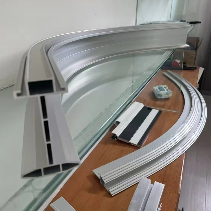
Aluminum Profile Bending
Thin Wall Aluminum Bending - 0.8 to 1.5 mm Walls
Bending 0.8-1.5 mm walls without cracking or wrinkling: 3x wall minimum radius, internal support, T5 temper, ±1° angular tolerance.
Product Details
A 1 mm wall bent to a 20 mm radius is not a scaled-down version of a 3 mm wall bent to a 60 mm radius. It is a different problem, because the two failure modes — wrinkling on the inside of the bend and cracking on the outside — both get worse as the wall thins, and they get worse at different rates.
We bend profiles with walls from 0.8 to 1.5 mm in L, U, V and small-radius forms, with a reference angular tolerance of ±1° and a minimum formed dimension of 10 mm. This page is about why thin-wall bending needs different tooling and a different mindset, not just a lighter touch.
Two failure modes, two mechanisms
When a profile bends, the material on the inside of the curve has to shorten and the material on the outside has to stretch. Both are driven by the radius relative to the wall thickness, and both become harder as that ratio grows.
| Inside of the bend | Outside of the bend | |
|---|---|---|
| Stress | Compression | Tension |
| Failure mode | Wrinkling, then folding | Necking, then cracking |
| What governs it | Buckling resistance, which scales with wall thickness squared | Ductility reserve, which is consumed by the temper |
| How it shows | A wavy inner flange, visible immediately | A hairline on the outer corner, sometimes only after anodising |
| How it is prevented | Internal support, larger radius, slower forming | Larger radius, softer temper, better surface finish on the die |
Buckling resistance falling with the square of the wall thickness is the reason thin-wall bending is a different discipline. Going from 2 mm to 1 mm does not halve the wrinkling resistance — it divides it by roughly four. That is why a thin-wall part needs internal support where a 2 mm part needed none.
The radius rule: 3× wall, not 1.5×
For a conventional wall of 2 mm or more, a radius of 1.5–2 times the wall is often workable. For 0.8–1.5 mm walls, a radius of at least 3 times the wall is the practical floor, and even that assumes good tooling and a T5 temper.
What happens below that:
- At 2× wall the outer fibre strain approaches the elongation limit of T6, and the inner flange starts to wrinkle unless it is fully supported.
- At 1.5× wall the outer corner is at or beyond the ductility of most tempers, and cracking is likely even with a perfect die.
- Below 1.5× wall the geometry is not a bend any more — it is a fold, and the material has to be formed hot, in a soft temper, or joined instead of bent.
So when a design calls for a sharp corner on a thin wall, the honest options are: increase the radius, change the temper, switch to a welded or riveted corner, or machine the corner from solid. Bending it as drawn is not on the list.
Internal support: what actually works
A thin-wall hollow or channel collapses at the bend unless something holds the section from inside. Three methods, in order of how often they are the right answer:
Polyurethane or elastomer insert. A compressible core is pushed into the cavity before bending and pulled out afterwards. It supports the walls without marking, it tolerates a changing section, and it is the default for closed hollow profiles. It works to moderate radii; at tight radii it compresses too much and stops supporting.
Low-melting-point alloy or wax filler. The cavity is filled with a solid that melts out afterwards. This supports the wall almost as well as a steel mandrel and can be removed from a shape that a mandrel could not be withdrawn from. It costs a process step per part and it is the right answer for tight radii on a closed section with a complex interior.
Steel mandrel. The strongest support, and the most limited: it has to be withdrawn after bending, so the bend has to be reachable from an open end. It marks the inner surface, which matters if that surface is visible.
For an open section — an L, a U, a channel — the support goes on the flanges instead: a pressure pad or a wipe die holds the flange against the punch so it cannot buckle. That is a tooling change, and it is why two shops with the same press can get different results on the same part.
Springback, and why thin walls are worse
Springback is the elastic recovery after the forming force is removed. The amount depends on the ratio of elastic strain to plastic strain at the bend, and on a thin wall the elastic fraction is larger — there is less material through the thickness to carry the plastic deformation, so more of the bend comes back.
The practical consequences:
- Over-bend is mandatory. The tool has to be set past the target angle, and the amount is determined by trial on the actual material.
- Batch-to-batch variation is real. Two heats of the same alloy and temper can differ by enough to move the angle by a few tenths of a degree. A process that is set once and run for months will drift.
- Temperature matters. A cold workshop in winter and a warm one in summer produce different springback on the same setting.
- Compensation is cheaper than correction. Setting the angle by over-bend and checking the first piece is normal. Straightening a bent thin-wall part to correct the angle introduces new stress and often marks the surface.
The ±1° reference tolerance is achievable, and it is achievable because the process is checked and adjusted, not because the machine holds it by itself.
Surface: the place thin-wall parts fail quietly
An anodic layer is typically 10–25 µm thick. A tool mark deeper than that cuts through the coating and shows as a bright line on an otherwise uniform surface. On a 3 mm wall this is a cosmetic issue; on a 1 mm visible part it is the reason the batch is rejected.
The controls that matter:
Protective film. A peel-off film on the visible face during forming prevents contact marks from the die. It has to be removed before anodising, and it adds a handling step per part.
Polished tooling. The die and wipe surfaces are polished to remove the tool marks that would transfer to the part. This is a maintenance item: a polished die stops being polished after a few thousand cycles.
Lubrication. Thin-wall forming needs consistent lubrication, because a dry patch increases friction, which increases the local strain, which is where the crack starts. Lubricant choice also has to be compatible with the pre-anodising cleaning process.
No post-bend straightening. If the angle is wrong after bending, correcting it in a press leaves marks and stress. Better to set the over-bend correctly on the first piece.
Specifications
| Item | Reference value |
|---|---|
| Wall thickness range | 0.8–1.5 mm |
| Bend types | L, U, V, small-radius curving |
| Minimum formed dimension | 10 mm |
| Angular tolerance | ±1° |
| Minimum bend radius | ≥3× wall (practical floor) |
| Preferred temper | T5: lower springback, better ductility |
| Internal support | Elastomer insert, low-melting filler, or steel mandrel, per section |
| Surface protection | Peel-off film plus polished tooling for visible faces |
| Forming speed | Low speed, controlled, to limit local strain rate |
| Alloys | 6063-T5 preferred; 6061-T6 where strength is required |
| Surface treatment after bending | Anodising, hard anodising, powder coating |
| Standard | GB/T 6892-2023, ISO 9001 |
Thin wall versus conventional wall, side by side
| Conventional, ≥2 mm | Thin wall, 0.8–1.5 mm | |
|---|---|---|
| Bend radius | ≥1.5–2× wall | ≥3× wall, mandatory |
| Temper | T5 or T6 acceptable | T5 preferred; T6 high risk |
| Cracking risk | Low | High; needs controlled strain |
| Wrinkling risk | Low | High; needs internal support |
| Surface protection | Normal handling | Film plus polished tooling, mandatory on visible faces |
| Forming speed | Can be fast | Low speed, monitored |
| Inspection | Angle and radius | Angle, radius, wall thinning, and coating integrity after anodising |
Where it does not fit
- The radius is below 3× the wall. Cracking and wrinkling are both likely. Increase the radius, change the temper, or form the corner another way.
- The part is 6061-T6 and the radius is at the limit. T6 has little ductility left. Bend in T5 or in a softer temper and age afterwards, accepting the distortion risk that comes with the heat treatment.
- The hollow section cannot be filled and cannot be reached by a mandrel. Without internal support the section will collapse. If a low-melting filler is not acceptable in your process, the part is not bendable.
- You need a Class A visible anodised face on the outside of a tight bend. Even with film and polished tools, stretch marks can appear. If the face must be flawless, plan on painting or on machining after forming.
- The part will be anodised before bending. The coating cracks on the outer fibre. Sequence it: bend, then anodise.
- The tolerance is tighter than ±1° on a thin wall in T6. Springback variation between batches will exceed it. Either accept a wider tolerance or move the requirement to a machined feature.
- Volume is very low and the section is custom. Tooling for supported thin-wall bending is not trivial. For a handful of parts, consider a welded assembly instead.
What to send for a quote
Send the section drawing with the wall thickness dimensioned, the bend drawing with radius and angle, the alloy and temper, the quantity, and which face is visible. Tell us whether the profile is hollow or open, because that decides the support method and the feasibility more than anything else on the drawing.
We will reply with the achievable radius for your wall, the support method we would use, whether the temper needs to change, the tolerance we can confirm on the angle, and the surface protection needed. If the radius is below the material's limit, that goes in the reply rather than in a reject note.
FAQ
What is the difference between thin-wall and conventional bending?
Three things. The minimum radius goes from about 1.5–2 times the wall to at least 3 times the wall. Internal support becomes mandatory rather than optional, because buckling resistance falls with the square of the thickness. And surface protection becomes a process requirement, because a tool mark deeper than the anodic layer is a visible defect.
What is the thinnest wall you can bend?
Reference 0.8 mm, in a T5 temper, at a radius of at least 3 times the wall. Below 0.8 mm the process becomes a forming specialty rather than a bending job, and the honest answer is usually a different design. The value on your order is set by your drawing, and we confirm feasibility on the actual section before quoting.
What angular tolerance can you hold?
Reference ±1°, achieved by setting over-bend against the first piece and checking through the run. On a thin wall the springback varies with heat and with workshop temperature, so the process is monitored rather than set once. Tighter than ±1° on a thin wall in T6 is not reliable.
Why does the wall crack on the outside of the bend?
Because the outer fibre has to stretch, and the amount of stretch is set by the radius relative to the wall. If the strain exceeds the remaining ductility of the temper, the material necks and then cracks. 6061-T6 has little ductility left, which is why it cracks at radii where 6063-T5 is comfortable. The fix is a larger radius or a softer temper.
Why does the inside of the bend wrinkle?
Because the inner wall is in compression and a thin wall buckles before it compresses. The fix is internal support: an elastomer insert for moderate radii, a low-melting filler or a mandrel for tight ones. On an open section the equivalent is a pressure pad holding the flange against the punch.
Can I have it anodised after bending?
Yes, and that is the correct order. Anodising after bending gives a continuous coating; bending after anodising cracks the coating on the outer fibre and the crack shows as a bright line. Tell us the finish at enquiry so the surface protection during forming matches it.
What happens if the angle is wrong after bending?
It is corrected on the press, and correction leaves marks and residual stress. The better route is to set the over-bend correctly on the first piece and check it through the run. On a thin visible part, a corrected angle often costs more than the part.
Send your drawing
Email the section drawing with the wall thickness, the bend geometry, the alloy and temper, and the visible face to linjunbing@truetrustlv.com, or send it on WhatsApp at +86 136 6644 0600. You will get the achievable radius, the support method and a written tolerance statement.
GET A QUOTE
Once you have submitted your requirements, we will contact you as soon as possible regarding your product inquiry.:Thin Wall Aluminum Bending - 0.8 to 1.5 mm Walls