
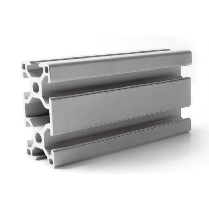
Industrial aluminum profiles
8-3060 T-Slot Aluminum Profile - 30 x 60 mm, 8 mm Slot
8-3060 profile: 30x60 mm, 8 mm slot, 6063-T5, 2.0 mm wall, 1.60 kg/m, I 13.20 cm4 on 60 mm axis, 3.50 on 30 mm. Door and side frames.
Product Details
Short answer: 8-3060 is a 30 × 60 mm rectangle in the 8-series: 8 mm slot, 6063-T5, 2.0 mm wall, 1.60 kg/m, with 13.20 cm⁴ on the 60 mm axis and 3.50 cm⁴ on the 30 mm axis. That 3.8-to-1 ratio is the largest in the range, so this profile is only worth using when the load direction is fixed and the 30 mm face is valuable. Working reference: about 0.22 mm deflection at 1 m with 10 kg on the strong axis. Section and tolerance are set by your drawing.
What it is used for
It builds frames that must be stiff in one plane while staying thin in the other: door frames, equipment side frames, wall-mounted columns, narrow machine surrounds, panel dividers, and the perimeter frame of a guard where the panel is in the 60 mm plane and the frame has to be slim when seen from the side.
A door is the clearest case. A door leaf carries its own weight and takes a push, both of which bend it in the plane of the leaf, so the frame member needs depth in that plane. But the door also has to be thin, so the same member has to be narrow in the other direction. A 30 × 60 with the 30 mm face outward gives depth where the bending is and a slim edge where the appearance matters.
Wall-mounted columns are the other case. The member stands off the wall by 30 mm and provides depth against a load applied parallel to the wall, which is exactly what a rectangle on its edge does.
Specifications
| Item | Value | Note |
|---|---|---|
| Section | 30 × 60 mm rectangular | 8-series, 8 mm slot |
| Alloy and temper | 6063-T5 | Standard for the range |
| Wall thickness | 2.0 mm | |
| Weight | 1.60 kg/m | 10 percent above 8-4040 |
| Moment of inertia, 60 mm axis | 13.20 cm⁴ | 1.55 times 8-4040 |
| Moment of inertia, 30 mm axis | 3.50 cm⁴ | 41 percent of 8-4040 |
| Ratio between axes | 3.8 to 1 | Largest directional ratio in the range |
| Deflection, 1 m, 10 kg, strong axis | About 0.22 mm | Own weight excluded |
| Deflection, same load, weak axis | About 0.83 mm | Near 8-3030 behaviour |
What the 3.8-to-1 ratio means in practice
On its strong axis this profile is better than 8-4040: 13.20 against 8.52 cm⁴, at 10 percent more weight. On its weak axis it is 3.50 cm⁴, which is worse than a 30 × 30 square and only 41 percent of the 4040. So the same member is either stiffer than the general-purpose section or weaker than the smallest square, depending on which way it is turned.
No other stocked profile has this spread. 8-4080 is 39.00 against 13.20 in the other direction, a ratio of 2.95. 10-4590 is 58.00 against 15.50, a ratio of 3.74. The 3060 at 3.8 is the most extreme, which means it rewards correct orientation more than any other section and punishes a mistake more severely.
The practical consequence is that this profile should only be used where the load direction is genuinely fixed by the design. On a door leaf, it is fixed. On a general frame where the load might come from either direction, the square is the safer answer.
Where this fits
It fits when one plane carries the bending, when the other dimension is a space or appearance constraint, and when the load direction is fixed by the design rather than by preference.
Where it does not fit: if the member could be loaded in either plane, use 8-4040 and accept the extra width. If the span is long and the load heavy, 8-4080 with 39.00 cm⁴ is the better shape because it puts more material at depth. And if the frame is a general structure rather than a door or a wall column, the directional bet is not worth taking.
Three things to get right
Mark the orientation on the drawing, and on the part. With a 3.8-to-1 ratio, a member fitted 90 degrees out is not slightly wrong, it is a different structure. On a door frame that error shows up as a leaf that sags at the handle side; on a wall column it shows as a bracket that flexes. The drawing should carry the orientation for each member, and where the workshop can, the part should be marked so the assembly cannot go wrong silently.
The joint at a corner needs thought. Where a 3060 meets another member at 90 degrees, the bracket has to span a 30 mm face and a 60 mm face, and the moment from the door load goes through it. A corner bracket sized for 4040 may be marginal here even though the member is stiffer, because the member now delivers a larger moment into a small face. On a door, a corner gusset or a mitred and bolted joint is often the right detail.
The 30 mm face limits the fittings. An 8 mm slot on a 30 mm face leaves little material either side of the slot, so the bracket footprint is small. Heavy hinges and long arms may not have enough face to sit on. That is worth checking before the section is chosen, because a door that needs a heavy hinge may be better on 4040 despite the extra width.
What to send for a quote
- The frame or door drawing, with the orientation of each member marked
- Load and span, and which plane carries them
- The hinge and bracket types, so the face width can be checked against them
- Cut lengths and machining, including mitres if the corners are mitred
FAQ
What tolerance can you hold?
Cut length and machined features are held to the tolerance on your drawing, with end and mitre cuts square and matched so a mitred corner closes without a gap. The value on your order is set by your drawing, and on a door frame the diagonal is often the figure worth agreeing, because a small length error becomes a visible skew.
Is it stiffer than 8-4040?
On the 60 mm axis yes, at 13.20 against 8.52 cm⁴, for 10 percent more weight. On the 30 mm axis no, at 3.50 against 8.52, which is 41 percent. So the answer depends entirely on orientation.
Why is the ratio between the axes important?
Because it tells you how much a mistake costs. At 3.8 to 1, fitting the member the wrong way round changes it from stiffer than a 4040 to weaker than a 3030. Sections with a lower ratio are more forgiving; this one is not.
What is it best used for?
Door frames, side frames, wall-mounted columns and narrow surrounds, where the bending is in one plane and the other dimension is constrained. It is less suitable for a general frame where the load direction is uncertain.
Can it be mitred?
Yes, and mitred corners are common on door frames because the joint is visible. A mitred joint needs the cut length to be accurate, since the two mitres share the corner, and it usually needs an internal corner bracket to carry the load.
What finish is usual?
Clear or black anodizing. On a visible door frame the finish is part of the product appearance, so the surface quality of the 30 mm face matters as much as the section.
Next step
Send the drawing with the member orientations and the hinge details. We will cut and machine to your drawing and flag any corner where the bracket looks undersized for the load.
Email: linjunbing@truetrustlv.com | Call or WhatsApp: +86 136 6644 0600
GET A QUOTE
Once you have submitted your requirements, we will contact you as soon as possible regarding your product inquiry.:8-3060 T-Slot Aluminum Profile - 30 x 60 mm, 8 mm Slot