
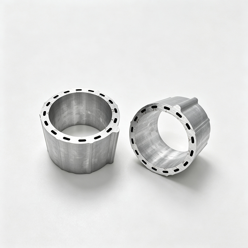
Custom Aluminum Profiles
Motor Housing Aluminum Profiles - Extruded, Machined, Anodized
Extruded motor housings with integral fins, slots and cable routes: 6063/6061, stator bore ±0.02-0.04 mm, bearing seat ±0.03 mm, anodized.
Product Details
Short answer: a motor housing does four jobs at once — it locates the stator, carries heat out of the windings, seals the end covers, and holds the rotor concentric with the stator bore. Only one of those is a strength requirement. We extrude housings with integral cooling fins, mounting slots and cable routes in 6063-T5, 6061-T6 or 6005A-T6, hold the stator bore to ±0.02–0.04 mm as extruded and the bearing seat to ±0.03 mm machined, and confirm the achievable values against your drawing before the die is cut.
Four jobs, and which one actually limits the design
Most housing drawings specify alloy and wall thickness as if the part were a pressure vessel. The requirements that really decide whether the motor runs cool and quiet are different:
- Locate the stator. The stator core is pressed or shrunk into the bore. If the bore is oval or tapered, the fit pressure is uneven, the core distorts, and the air gap between stator and rotor varies around the circumference. A varying air gap produces unbalanced magnetic pull, which shows up as noise and vibration at twice line frequency.
- Carry heat. The winding is the heat source and the housing is the path to ambient. Between them sit two interfaces — winding to core, core to housing — and both are contact resistances that dominate the thermal chain far more than the aluminium's conductivity does.
- Seal. The end cover joint is a flat face with a gasket or an O-ring. Flatness and surface finish decide whether it seals; a 0.05 mm bow across a 120 mm flange is a leak path on a gasket joint.
- Look finished. For a servo on a machine tool or a drive unit in a vehicle, the housing is a visible surface, and anodised aluminium reads as a finished part in a way painted cast iron does not.
Extruded housing or die casting
Both are correct for different volumes and different sections, and the choice is usually made on price alone when it should be made on tolerance and on how many operations the section can absorb.
| Item | Extruded housing | Die-cast housing |
|---|---|---|
| Dimensional tolerance | ±0.02–0.04 mm on section features | Typically ±0.1–0.3 mm, machining needed on fits |
| Wall uniformity | Controlled by the die; even around the bore | Varies with flow; thick sections can shrink porous |
| Integrated fins, slots, cable routes | In the section, at no extra operation | Possible, but draft angle and ejector marks limit detail |
| Porosity | None — the section is solid metal | Gas and shrinkage porosity possible; pressure-tightness needs care |
| Surface for anodising | Clean, uniform, takes a bright film | Porosity and cold shots show through the film |
| Economic volume | Low to medium, and multi-variety families | High volume, single design |
| Length flexibility | Cut to any length from one die | One length per tool |
The practical summary: below a few tens of thousands of units a year, or whenever the motor family has several lengths from one diameter, extrusion wins because the die is cheap, the section is sound, and length is a saw setting rather than a new tool. Above that, die casting wins on cycle time. There is also a hybrid that works well — an extruded body with die-cast or machined end covers — which keeps the bore accurate and puts the complex geometry where it is cheap.
The stator fit is the whole job
A stator core in a housing is an interference fit, and the interference has to survive the thermal cycle. Aluminium expands at 23.6 µm/m·K and the steel core at about 12, so when the motor heats up the housing grows away from the core. A fit that is correct cold can go loose at 120 °C, and a loose core in a housing is a noise source, a hot spot and eventually a failure.
Two things follow. First, the interference is calculated for the hot condition, not the cold one, and that calculation needs the housing's actual wall thickness — a thin wall expands more freely than a thick one and relaxes the fit faster. Second, the bore has to be round and straight within the interference budget. A bore with 0.04 mm of ovality consumes most of a 0.05 mm interference before the motor is even warm.
This is why the bore is the feature we inspect hardest and why we prefer to finish it by boring rather than by drawing it to size. Drawing gives a good bore; boring gives a bore that is round, on size and coaxial with the bearing seat, and the difference shows up as noise at speed.
Where the heat actually goes
Winding copper to stator core, core to housing, housing to air. Each step has a resistance, and the aluminium is the least of them. What the housing contributes is surface area and fin geometry, and fin geometry has a hard limit that is worth knowing before the drawing is fixed.
A fin works by being cooler than its base, and it stops being useful when it is long enough that its tip is at ambient. For aluminium in still air, the point of diminishing return arrives at a fin height of roughly six to eight times the fin thickness; beyond that you are adding mass, not cooling. A 1.5 mm fin is worth having up to about 10 mm of height. A 40 mm fin at 1.5 mm thickness is mostly decoration — and it is also difficult to extrude, because a 27:1 aspect ratio fin deflects under its own exit pressure.
What does work: more fins at a workable aspect ratio, a thicker base so heat spreads laterally before it climbs, and air actually moving across the fins. A forced-air housing with 12 mm fins and a fan outperforms a natural-convection housing with 40 mm fins, and it is easier to extrude.
Specifications
| Item | Range and note |
|---|---|
| Alloys | 6063-T5 general, 6061-T6 high power and EV drive, 6005A-T6 heavy duty |
| Circumscribed circle | Up to 700 mm; most housings run 60–200 mm |
| Wall thickness | 1.2–12 mm typical; even walls preferred around the bore |
| Bore tolerance as extruded | ±0.02–0.04 mm on critical dimensions |
| Bearing seat, machined | ≤ ±0.03 mm diameter and position, per drawing |
| End-cover face flatness | ≤ 0.02 mm across the sealing face |
| Bore roundness after boring | Held within the interference budget stated on your drawing |
| Machined tolerance | ±0.01 mm typical, ±0.005 mm boring |
| Maximum length | 6,500 mm machined |
| Surface | Anodised 10–15 µm, hard anodised 25–50 µm on wear faces, powder coated |
| Integrated features | Cooling fins, mounting slots, cable route, sensor pocket, nameplate recess |
| Inspection | CMM report on bore and bearing seat; material certificate per batch |
| Trial quantity | From 50 kg for a development build |
| Reference standard | GB/T 6892-2023; ISO 9001 process control |
Alloy choice by motor type
| Motor | Typical alloy | What drives it |
|---|---|---|
| Servo, 100 W–5 kW | 6063-T5 or 6061-T6 | Bore accuracy, fin detail, cosmetic finish |
| Stepper | 6063-T5 | Dimensional accuracy and surface, low cost |
| EV traction motor | 6061-T6 | Strength, fatigue under road load, thermal mass |
| Industrial pump or fan motor | 6063-T5 / 6005A-T6 | Corrosion resistance, long straightness, low cost |
| Robot joint motor | 6061-T6 | Mass at the joint, stiffness, bore precision |
| Elevator traction machine | 6005A-T6 / 6061-T6 | Load capacity, bearing seat accuracy, safety factor |
Surface treatment: two decisions people get wrong
The first is anodising the bore. An anodic film is an insulator, with a breakdown voltage that rises with thickness — a 15 µm film holds a few hundred volts, a 50 µm hard film considerably more. On a motor where the shaft voltage is a real phenomenon, a coated bore and coated end faces can be a deliberate insulation feature. On a motor where the housing is the protective earth path, the same coating is a fault, because the earth connection now depends on a masked spot nobody specified. Decide which one your motor needs and mark it on the drawing.
The second is coating after boring. Anodising grows roughly half the film thickness per face, so a bore cut to final size will be undersize after coating. Either mask the bore, or bore oversize by twice the film, or bore after coating. All three are valid; picking none of them is how a housing arrives that will not accept its stator.
The third, less obvious, is colour consistency. Anodised shades shift slightly between batches because bath age and alloy heat move the tone. On a housing that is visible next to another housing from an earlier order, that shift is noticeable. If colour match matters, send a sample to match against and keep it on file — matching to a physical part is far more reliable than matching to a screen.
Where it does not fit
- A housing with internal cooling channels, a helical water jacket or a complex internal core. Those are casting or fabricated assemblies; an extrusion can only produce a constant cross-section.
- A housing with a flange whose shape changes along the length, or with bosses on more than one axis. Machining can add them, but at that point the economics usually favour a casting.
- Motors that must be pressure-tight to a specification. An extrusion is sound metal, but the seals are at the end covers, and a pressure-tight claim needs a tested assembly, not a section.
- Very high volume, single length. Above a few tens of thousands of units a year, die casting wins on cycle time and the extrusion's tolerance advantage is no longer worth the machining.
- Housings that are welded to a frame or a bracket after machining. Weld heat will distort the bore, and the bore is the feature you paid for.
What to send for a quote
- The housing drawing with the stator bore, bearing seat and end-cover face all dimensioned, plus the datum scheme
- The stator outside diameter and the intended fit — press, shrink or clearance — since that sets the bore tolerance budget
- The motor's rated power and the heat it rejects, so the fin geometry can be checked rather than copied
- The alloy and temper, or the duty and environment if the alloy is still open
- The sealing method at the end covers: gasket, O-ring or sealed with compound
- Whether the housing is on the protective earth path, which decides where coating is allowed
- The surface treatment, colour and any face that must stay bare
- Length, annual volume and whether the motor family uses several lengths from one bore, which is where extrusion is strongest
FAQ
What tolerance can you hold on the stator bore?
Reference ±0.02–0.04 mm as extruded on critical dimensions, and better than that after boring, with the bearing seat at ±0.03 mm and roundness held inside your interference budget. The value on your order is set by your drawing, and we confirm in writing what we can hold before tooling. If the bore has to be anodised as well, say so at quotation stage — the film grows into the bore and the allowance has to be planned, not discovered.
Is an extruded housing better than a die casting?
For low and medium volume, multi-length families and anything where the bore must be accurate without a lot of machining, yes. The section is sound metal with no porosity, the tolerance is roughly five times tighter, and length is a saw setting. For high volume in a single length, die casting is cheaper per part and the tolerance disadvantage disappears once you machine the fits anyway.
How do I know the fin design is enough?
Compare fin height to fin thickness. Beyond about six to eight times the thickness, additional height adds mass rather than cooling, because the tip is already close to ambient. If the motor still runs hot with a well-proportioned fin stack, the constraint is usually the winding-to-core or core-to-housing interface, not the fins — reducing contact resistance there buys more than adding fin area. We will say so rather than sell a taller fin.
Can you integrate the cable route and the mounting slots?
Yes, and that is one of the main reasons to extrude rather than cast. Cable routes, mounting slots, sensor pockets and nameplate recesses can all be part of the section, which removes operations and removes the risk of a drilled hole breaking into a cavity. Features that run along the length are free; features that cross the section, such as a radial hole, are machined.
Will anodising affect the fit?
It grows the surface by roughly half the film thickness per face — about 7–8 µm at 15 µm film. On a stator bore that is inside the interference budget and worth accounting for; on a bearing seat it is not negligible. The standard answers are to mask the fit, cut it oversize by twice the film, or finish it after coating. Tell us which fits are critical and we set the allowance before the parts reach the bath.
What is the smallest quantity that makes sense?
A development build starts at 50 kg, which is enough to machine and test a real housing rather than a coupon. Below that, machining from a stock tube is usually the cheaper route and we will say so. The die is H13 nitrided steel with a working life of 50,000 press cycles or more, so once the design is stable the tool is not the constraint.
Send your drawing
Email linjunbing@truetrustlv.com with the housing drawing, the stator diameter and the fit. If the section is not settled, send the motor envelope, the rated power and the ambient it runs in, and we will propose a fin and wall arrangement rather than quote a shape that will run hot. You will get a section proposal, a machining and coating plan, and a price — reviewed by an engineer.
WhatsApp: +86 136 6644 0600
GET A QUOTE
Once you have submitted your requirements, we will contact you as soon as possible regarding your product inquiry.:Motor Housing Aluminum Profiles - Extruded, Machined, Anodized