
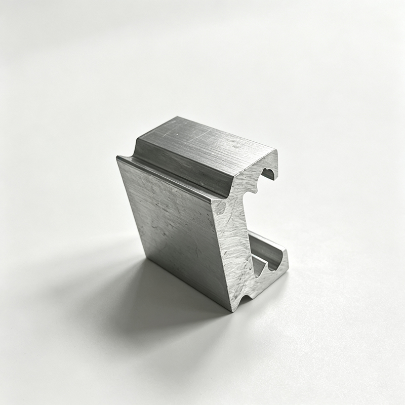
Custom Aluminum Profiles
Robot Structural Aluminum Profiles - Extrusion and Machining
Aluminum profiles for robot arms and bases in 6061-T6, 6082-T6 or 7075-T6: stress relieved, joint bores to ±0.03 mm, straightness 0.2 mm/m.
Product Details
Short answer: a robot arm section is sized by dynamics, not by strength. Mass near the wrist costs acceleration, stiffness sets the natural frequency that decides settling time, and residual stress decides whether the arm still hits the same point in twelve months. We extrude arm and base sections in 6061-T6, 6082-T6 or 7075-T6 up to a 700 mm circumscribed circle, relieve stress to a measured residual level, and machine joint bores to ±0.03 mm. The value on your order is set by your drawing, and we confirm what we can hold before the die is cut.
Three numbers that decide whether the arm is any good
Robot structural parts are usually specified as if they were machine frames: strength, straightness, corrosion. Those are the easy requirements. The three numbers that separate a good arm from a mediocre one are less often written on a drawing.
- Mass at the wrist. Every kilogram on the forearm is a kilogram the shoulder motor accelerates and the arm structure has to hold against gravity at full extension. Arm sections are designed to lose mass at the far end and keep it at the base, which is why topology optimisation on a robot arm produces a tapering, ribbed profile rather than a constant box.
- First natural frequency. For a structure, f ∝ √(k/m). Stiffening raises f by the square root of stiffness, lightening raises it by the square root of the mass reduction. Both matter, and on an arm the mass term is often the cheaper one to move. A robot that rings at 12 Hz will not hold a 40 Hz control loop no matter how good the encoder is.
- Residual stress. A profile that is straightened by roller bending carries locked-in stress. Machine one face and it bows; put it in a warm shop and it creeps. The error is small in absolute terms and large in the context of a repeatability spec measured in hundredths of a millimetre.
Why temper does not buy stiffness, and what to do instead
Modulus is about 69 GPa across every 6xxx and 7xxx alloy, in every temper. Upgrading an arm from 6061-T6 to 7075-T6 raises yield from roughly 240 MPa to roughly 500 MPa and leaves stiffness unchanged. If the arm is ringing or sagging, 7075 buys nothing — it costs more, extrudes far worse, cannot be brought to a bright anodised finish and cannot be welded at all in any practical sense.
What actually raises stiffness is geometry: depth in the bending plane, a closed box rather than an open channel, ribs on the faces that carry compression, and joints that carry moment. On a hollow arm section the internal rib is worth more than the wall thickness, because it prevents the section from ovalising under torsion. An arm that has been thickened instead of ribbed is heavier, no stiffer in torsion, and slower.
Where high strength does earn its place is at the joints: bolt bosses, bearing seats, clamp collars, keyways — the places where the section is cut into and the local stress is no longer a beam stress. That is where 6082-T6 and 7075-T6 make sense, and why some arms are a 6061 body with a 6082 end block rather than one alloy throughout.
Specifications
| Item | Range and note |
|---|---|
| Alloys | 6061-T6 general arm and base, 6082-T6 high-rigidity, 7075-T6 extreme load |
| Circumscribed circle | Up to 700 mm |
| Extruded tolerance | ±0.02–0.04 mm on critical dimensions |
| Joint mounting tolerance | ≤ ±0.03 mm on bore position and diameter, per drawing |
| Machined tolerance | ±0.01 mm typical, ±0.005 mm boring on a five-axis centre |
| Straightness | ≤ 0.2 mm/m as standard, 0.1 mm/m on request |
| Coaxiality | ≤ 0.05 mm between joint bores on the same axis |
| Flatness | ≤ 0.06 mm per 300 mm on mounting faces |
| Residual stress relief | Press quench plus two-stage artificial ageing plus natural ageing; ≥ 85% relief |
| Maximum machined length | 6,500 mm |
| Surface | Anodised 10–15 µm, hard anodised on wear faces, powder coated |
| Inspection | CMM report per batch on the critical features; material certificate |
| Reference standard | GB/T 6892-2023 high-precision grade; ISO 9001 process control |
Alloy choice by robot type
| Application | Typical alloy | What drives the choice |
|---|---|---|
| Industrial arm, 6-axis, 5–50 kg payload | 6061-T6 with 6082-T6 end blocks | Fatigue at the joint, stiffness at the wrist, weldability if a bracket is added |
| Collaborative arm | 6061-T6 | Low mass at the far end, low residual stress, cosmetic anodised finish |
| SCARA horizontal arm | 6061-T6 / 6082-T6 | High-speed reciprocation; torsional stiffness and low inertia dominate |
| AGV / AMR chassis frame | 6061-T6 / 6005A-T6 | Impact tolerance, long straightness, easy fixturing |
| Heavy payload or press-tending | 6082-T6 / 7075-T6 | Bending moment at full extension; strength, not stiffness, becomes critical |
| Gantry and seventh axis | 6061-T6 / 6082-T6 | Span-driven deflection; depth of section in the bending plane |
Residual stress, and why it shows up months later
An extruded profile leaves the press at 500 °C and is quenched, which locks in stress. It is then stretched or rolled to straighten it, which adds more. If that stress is not addressed, it does not sit quietly: it redistributes every time material is removed, and it relaxes slowly at room temperature for weeks.
The sequence that controls it is quench, then two-stage artificial ageing, then natural ageing, then machining. On a part with tight bore tolerances we machine in two passes with a delay between them, so the first cut releases what it is going to release and the second cuts to final size. On the highest-precision parts, a stress-relief cycle is run between roughing and finishing. Skipping this is the most common reason a robot arm is accurate on the day of assembly and drifts by the end of the quarter.
Related and often missed: anodising is a room-temperature process that grows a film on the surface, but the film is brittle and puts the surface in tension. On a thin wall, hard anodising a whole arm can pull it out of straightness. Coat the wear faces, mask the rest, and check straightness after coating rather than before.
Machining a joint bore that stays round
The joint bore is where the reducer or the servo mounts, and it is the feature that decides repeatability. Three things matter. The bore must be round, not just on size — an oval bore clamps the bearing and the arm loses stiffness at exactly the point where it needs it. The bore axis must be square to the mounting face; a 0.02 mm squareness error across a 100 mm flange is a visible tilt at the end of a 1.5 m arm. And the bore must be positioned from a datum that is stable, which means from machined faces, never from the extrusion's outside surface.
We bore on a five-axis centre in one setup where the part allows, because a second setup reintroduces the fixturing error it was meant to remove. Where the part is too long for one setup, we use a common datum and verify with a CMM report rather than trusting the machine's positioning.
Where it does not fit
- An arm that must hold sub-0.02 mm repeatability at full extension over a long span. Aluminium's modulus is a third of steel's; at some span the section becomes too large to be practical and a steel or composite structure is the honest answer.
- A structure that sees high-cycle fatigue at a weld. Extruded 6xxx welds lose most of its temper in the heat-affected zone, and a welded joint in a reversing load is a crack initiation site. Bolt or bond instead, or design the weld out.
- Continuous sliding wear on a bare surface. Anodising gives 200–300 HV; a hardened steel way or a linear rail is the right answer for a wear surface under load.
- Parts that must be mirror-polished after anodising on a 7075 section. High-copper alloy produces a dark, non-uniform film that cannot be polished back to a bright finish.
- Very low volume with no repeat. A die plus setup is hard to justify for three arms; a machined-from-plate or a stock-section design will be faster and cheaper.
What to send for a quote
- The arm or link drawing with joint bore positions, diameters and the datum scheme
- The payload and the arm's reach, so the section can be checked on deflection at full extension rather than guessed
- The control bandwidth or the settling time you need, which sets the natural frequency target
- The alloy and temper, or the duty cycle if the alloy is still open
- Which features are fits — bores, dowel holes, mounting faces — and their tolerances
- The surface treatment, and which faces must stay bare for grounding or for a bearing seat
- Whether the part will be welded to anything, since that decides whether 7075 is even possible
- Volume, repeat frequency and whether the section is likely to change after the prototype
FAQ
What tolerance can you hold on a joint bore?
Reference ±0.03 mm on bore position and diameter, with ±0.005 mm available when the bore is finished on a five-axis centre in a single setup. The value on your order is set by your drawing, and we state in writing what we can confirm for your part before production. Where the bore has to survive anodising, the allowance is built in or the bore is masked — a coated bore that was cut to final size will not accept the bearing.
Should I use 7075-T6 for a robot arm?
Only if strength, not stiffness, is the limit. 7075-T6 gives roughly double the yield of 6061-T6 and identical modulus, so it does nothing for deflection or ringing. It also extrudes poorly, cannot be press-quenched, cannot be welded, and cannot be anodised to a bright finish. For most arms 6061-T6 with a well-designed section outperforms 7075-T6 with a poor one, at a fraction of the cost.
How do you stop the arm drifting out of tolerance over time?
By controlling residual stress before machining, not by tightening the machining tolerance. Quench, two-stage artificial ageing, natural ageing, then machine — and on critical parts rough, stress-relieve, then finish. We report a relief level above 85% and machine in two passes where the geometry allows. A part that is machined from a stressed blank will move, and no inspection at the machine will catch it because the movement happens afterwards.
Can the arm sections be welded?
They can be welded in 6xxx, and the weld will be sound, but the heat-affected zone loses most of the T6 temper and the joint becomes the fatigue-critical feature. If a bracket has to be attached, bolting into a machined boss or bonding with an engineered adhesive is usually better than welding. If welding is unavoidable, design the weld away from the highest bending moment and expect to re-machine any critical face afterwards.
What is the largest arm section you can produce?
Up to a 700 mm circumscribed circle on the 12,500 t press, machined to 6,500 mm. In practice arm sections are much smaller — the limit is rarely the press and usually the straightness after quench, because a large asymmetric section is harder to hold straight. Where a section would need to be very large, a fabricated box from four smaller extrusions is often lighter and stiffer than one big profile.
Do you supply the machined part or only the extrusion?
Either, and the machined part is the more useful purchase for most customers: extrusion, machining, anodising and inspection under one roof means one tolerance chain instead of three, and one party accountable when a bore is out. We also supply cut-to-length extrusion alone where the customer machines in-house, with the section tolerance and the straightness stated on the certificate.
Send your drawing
Email linjunbing@truetrustlv.com with the link drawing, the payload and the reach. If the section is not settled, send the envelope and the settling time you need, and we will propose a section that meets it instead of quoting a shape that cannot. You will get a section proposal, a stress-relief and machining plan, and a quotation reviewed by an engineer.
WhatsApp: +86 136 6644 0600
GET A QUOTE
Once you have submitted your requirements, we will contact you as soon as possible regarding your product inquiry.:Robot Structural Aluminum Profiles - Extrusion and Machining