
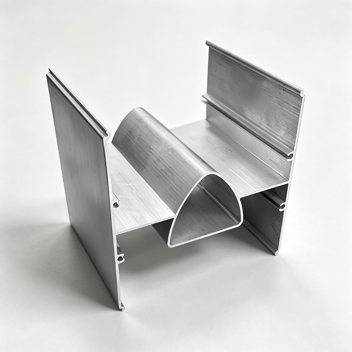
Custom Aluminum Profiles
Non-Standard Aluminum Profile Mold Opening - Custom Sections
Mold opening for non-standard aluminum sections: walls 0.6-50 mm, up to 700 mm circle, CAE flow-checked dies, ±0.02-0.04 mm on critical dims.
Product Details
Short answer: a non-standard section is not hard because it is unusual. It is hard because of four measurable ratios — wall thickness, aspect ratio, tongue ratio and the amount of asymmetry — and each one decides whether the die can be fed evenly. We design and cut the tool in-house, simulate the metal flow before steel is cut, extrude on 600–12,500 t presses up to a 700 mm circumscribed circle with walls from 0.6 to 50 mm, and hold ±0.02–0.04 mm on section dimensions. The value on your order is set by your drawing, and we tell you before the die is cut if a ratio in your section cannot be run.
Why a new section is a tooling problem, not a drawing problem
A standard profile exists because someone already solved its metal flow. A closed slot with even walls, a symmetric box, a simple angle — these fill evenly and come out straight. What makes a custom section difficult is not the shape you can see on the drawing; it is the shape the aluminium sees as it moves through the die.
Hot aluminium at 480–520 °C does not behave like a fluid in a pipe. It behaves like a very stiff, very hot solid being forced through a shape, and it will always take the path of least resistance. If one part of the section is a heavy mass and another is a 0.8 mm tongue 30 mm out on a limb, the metal arrives at the thin part late and cold, or not at all. The die designer's job is to slow the fast metal and speed the slow metal until the whole section exits at one velocity. That is done with bearing length — the land at the die exit — and it is the single most important variable nobody outside the trade ever looks at.
The four ratios that decide whether your section runs
Before quoting, we score a section on four numbers. They are worth knowing because they let you fix a design before it becomes a tooling cost.
- Wall thickness ratio. The thinnest wall divided by the thickest. A section with 1.2 mm walls and a 12 mm solid boss in the same plane is a 1:10 part, and the mass will starve the thin wall of pressure. Material is added to the thin side or taken off the thick side; the section is redesigned, not forced.
- Aspect ratio. Width divided by thickness of a protruding feature. A fin 40 mm tall and 1.5 mm thick is 27:1 and will deflect under its own exit pressure. Above roughly 15:1 the fin needs support, a taper, or a different alloy.
- Tongue ratio. The depth of a slot's tongue divided by its width. A deep narrow slot means a long, thin tongue of die steel with hot metal on three sides. Above about 3:1 that tongue deflects or breaks, and the fix is a porthole or bridge die, or splitting the feature into two parts joined later.
- Asymmetry. How far the centre of metal flow sits from the geometric centre. An asymmetric section exits with the fast side leading, which shows up as twist and as a bow that cannot be straightened out. The die is balanced with a flow-correcting pocket, and the section may be re-proportioned so the mass is symmetric.
Specifications
| Item | Range and note |
|---|---|
| Section types | Multi-slot integrated, deep cavity, asymmetric, profiled curved face, functional hybrid |
| Wall thickness | 0.6–50 mm; the ratio between min and max matters more than either number |
| Circumscribed circle | Up to 700 mm |
| Alloys | 6063-T5, 6061-T6, 6005A-T6, 6082-T6, 7075-T6 |
| Extruded tolerance | ±0.02–0.04 mm on critical dimensions |
| Key assembly tolerance | ≤ ±0.05 mm, per drawing |
| Machined tolerance | ±0.01 mm typical, ±0.005 mm on a five-axis centre |
| Maximum machined length | 6,500 mm |
| Surface | Anodised, hard anodised, powder coated, brushed, polished |
| Die material | H13 hot-work steel, nitrided; life ≥ 50,000 press cycles |
| Flow simulation | CAE check of fill, exit velocity and tongue stress before the die is cut |
| Trial quantity | From 50 kg for a development build |
| Reference standard | GB/T 6892-2023; ISO 9001 process control |
How the die is actually designed
The first pass is a flow model. We build the die cavity and the porthole or flat-face feed in CAE, then run the metal as a viscous body to see where it arrives first. Two outputs matter: the exit velocity map across the section, and the peak stress in any thin die feature. A section with a 2:1 velocity spread across its width will twist; a tongue above its stress limit will break mid-press and take the billet with it.
The second pass is bearing. At the die exit there is a land of hardened steel that the metal rubs against. A long land brakes the metal, a short land lets it run. By grading the land around the perimeter — long where the section is thick and fast, short where it is thin and slow — the exit velocity is levelled. This is why two dies for the same drawing from two suppliers can produce very different parts: the drawing is identical, the bearing is not.
The third pass is the run-in. The first billet through a new die tells you what the model did not: where the section runs hot, where it drags, where the surface tears. Bearings are polished back or built up, and the die is run again. A complex section may take several iterations before the first saleable length comes off the press, and that iteration is the real content of a tooling price.
What each section feature costs you
| Feature in your drawing | What it does to the process | How it is handled |
|---|---|---|
| Multiple closed slots in one section | Needs a porthole die with several feed ports; weld lines land in the wall | Ports positioned so weld lines fall on non-critical faces |
| Deep internal cavity | Long die tongue, hot on three sides, prone to deflection | Split tongue with a support bridge, or a two-part section joined after extrusion |
| Asymmetric mass distribution | Uneven exit velocity, twist and bow | Flow-balancing pocket on the heavy side; stretch-straighten after quench |
| Thin wall opposite thick wall | Thin side starves, thick side runs fast | Wall re-proportioned, or alloy changed to a freer-flowing 6063 |
| Profiled curved outer face | Contour accuracy depends on bearing and die finish | Bearing graded along the curve; profile checked on a contour gauge per batch |
| Sharp internal corner | Stress concentration in service and in the die | Minimum internal radius added; it costs nothing and prevents cracking |
Where a custom section stops making sense
A die is worth cutting when the section removes an operation or solves a problem no stock shape solves. It stops making sense in three situations that come up often.
First, when the annual volume is small and the section is a simple rectangle. There is a stock 40 × 40 with the right wall; buying it and machining the features will be cheaper than a die, a run-in and a minimum billet, and it will be available next week instead of next month. Second, when the design is still moving. A die locks the section; if the enclosure is going to change twice in the next six months, extrude a simple shape now and machine the features until the design settles. Third, when the feature you need is a precise bore or a flat face. Extrusion gives you a shape, not a tolerance; those features come off a machining centre either way, and paying a die to approximate them is wasted money.
Where it does not fit
- Sub-millimetre features repeated along a long section. Extrusion holds a profile, not a detail; that is a machining or a roll-forming job.
- A section with an undercut that has to be closed on all sides. A die cannot pull a closed shape out of itself, and a split die leaves a seam on the visible face.
- Genuine one-offs. A die plus run-in for a single length is almost never the right purchase.
- Parts that must be welded along their full length after extrusion. The weld heat will destroy the temper you paid for, and a welded assembly from simple sections is usually the better route.
- Sections where cosmetic appearance on every face is critical. Die lines, a weld seam or a pickup mark will appear somewhere; if there is no hidden face to put them on, plan for a finishing operation.
What to send for a quote
- The section drawing at 1:1 with wall thicknesses and all radii called out — a PDF and a DXF if you have both
- The alloy and temper, or the duty the part sees if the alloy is still open
- Which dimensions are functional fits and which are cosmetic, since that decides where the tolerance budget is spent
- The length required and whether it is one piece or cut multiples
- Any face that will be visible after assembly, so die lines and weld seams can be positioned away from it
- The expected annual quantity and whether the section is likely to be revised
- The surface treatment and colour, and whether it goes on before or after machining
A hand sketch with three dimensions is enough to start a feasibility opinion. We will tell you which ratio in it is the risk and what it would take to remove that risk — usually a wall change that costs nothing at design stage and a great deal after the die is cut.
FAQ
What is the thinnest wall you can extrude in a custom section?
Reference 0.6 mm on a small section in 6063, and 1.0–1.5 mm on a large or complex one. The value on your order is set by your drawing and confirmed in writing before tooling, because the wall cannot be judged on its own: a 0.6 mm wall in a 40 mm section with even support is routine, and the same wall 60 mm out on an unsupported fin is not. Send the section and we will state the thinnest wall we can hold and what it needs around it.
Why does my section come out twisted, and can it be fixed?
Twist comes from uneven exit velocity, which comes from uneven metal distribution. Either the die bearing is not balanced or the section is asymmetric enough that no bearing can balance it. Mild twist is removed by stretch straightening after the quench, which also stress-relieves the length. Heavy twist means the die has to be reworked, and if the asymmetry is in the drawing itself, the section is re-proportioned. It is not something to accept and machine around — a twisted section will move again after machining.
How accurate is an extruded section compared with a machined part?
Reference ±0.02–0.04 mm on critical section dimensions, against ±0.01 mm for a machined feature. That difference is why the process is normally split: extrude the shape, then machine the fits. Trying to hold a bearing fit in the extrusion means holding the whole length to a tolerance the process only achieves on selected dimensions, and paying for sorting at the press. Extrude for shape, machine for tolerance.
Can I get a section in 7075?
Sometimes, and rarely cheaply. 7075 has a narrow extrusion window, is quench-sensitive, and cannot be press-quenched to T6 the way a 6xxx can, so it needs a separate solution treat and age. It also cannot be brought to a bright anodised finish and welds badly. Where the requirement is strength, 6082-T6 usually covers it with far less process risk. Where 7075 is genuinely needed, we will quote it and say what the tooling risk looks like.
What is the difference between a flat-face and a porthole die?
A flat-face die has a single opening and the metal flows straight through; it works for solid sections and open shapes. A porthole or bridge die splits the metal into several streams around a central mandrel and re-joins them before the exit, which is the only way to make a hollow section with closed cavities. The re-joining leaves weld lines in the wall. They are sound — the metal is joined under pressure at temperature — but they are visible after anodising and they are a fatigue consideration, so their position is chosen deliberately.
Do I own the die?
The tool is built for your section and stays with the project for repeat orders, and the commercial terms are stated in the quotation rather than assumed. What matters practically is that the die is designed so a wall or a slot can be revised without cutting a completely new tool, because most sections change once after the first prototype build. Ask for that in writing at the quotation stage; it is a design decision, not a favour later.
Send your drawing
Email linjunbing@truetrustlv.com with the section drawing and the annual quantity. If the section is still open, send the envelope and what the part has to do, and we will propose a shape that extrudes cleanly rather than one that needs three die revisions. You will get a feasibility note naming the risk ratios, a tooling position and a price — reviewed by an engineer, not an auto-reply.
WhatsApp: +86 136 6644 0600
GET A QUOTE
Once you have submitted your requirements, we will contact you as soon as possible regarding your product inquiry.:Non-Standard Aluminum Profile Mold Opening - Custom Sections