
Custom Aluminum Profiles
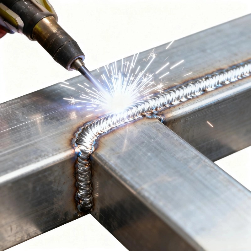
Welded Aluminum Profile Assemblies - Integrated Extrusion
Extrusion and welding designed together: section, joint and distortion allowance set at die stage. Weld strength 85% of parent, ±1 mm over 3 m.
Product Details
Short answer: when a profile is going to be welded, the section should be designed for the weld rather than the weld made to fit the section. That means planning the joint, the distortion allowance and the machining sequence while the die is still being cut, not after the extrusion arrives at a fabricator. We hold ±0.02–0.04 mm on the section, ±0.01 mm on machined features, weld strength at 85 percent of parent or better, and ±1 mm over 3 m on a welded assembly. The value on your order is set by your drawing, and we confirm what the assembly can hold before tooling.
Why splitting the work between two suppliers costs more than it looks
The normal route is: buy extrusion from an extruder, send it to a fabricator, weld it, machine it. Each party does its own job correctly and the assembly still comes out wrong, for a structural reason: the decisions that cause the problem are made on one side and the consequences are paid on the other.
The extruder chooses wall thickness, corner radii and section symmetry for extrusion reasons. Every one of those choices affects how the part will distort when welded. The fabricator then receives a section that may have a thick-to-thin transition exactly where the weld has to run, and does the best it can with fixtures and sequence. The machinist then has to hold a tolerance on an assembly that has already moved.
The integrated route makes those decisions together: the section is designed with the weld in mind, the distortion allowance is put into the extrusion, and the machining is planned to happen after welding on the faces that matter. It is not a commercial convenience, it is the only way to hold tolerance on a welded frame.
What welding does to aluminium, in numbers
Three properties drive every welding decision on a 6xxx extrusion, and they are all more severe than for steel.
- Thermal expansion of 23.6 µm/m·K. Roughly twice steel. A 2 m frame that heats to 200 °C near a weld grows 9 mm relative to its cold length, and it shrinks back on cooling against whatever restraint the fixture applies. That is where distortion comes from.
- Thermal conductivity about five times steel's. Heat spreads far from the weld, so the heat-affected zone is wide and the temper loss extends well beyond the visible bead. On 6061-T6, the HAZ drops toward the annealed condition, which is why the 85 percent figure is a target for a well-designed joint and not an automatic result.
- Strength loss in the HAZ. A 6061-T6 weldment is designed on the HAZ strength, not the parent strength. Friction stir welding retains far more because it never melts the metal, which is why it is the preferred process wherever the geometry allows.
Specifications
| Item | Range and note |
|---|---|
| Alloys | 6061-T6, 6063-T5, 6005A-T6, 5083 for welded assemblies that need corrosion resistance |
| Welding processes | MIG, TIG, gas-shielded, friction stir welding |
| Weld strength | 85% of parent metal or better with a designed joint; FSW retains more |
| Assembly accuracy after welding | ±1 mm over 3 m as a working figure, improved by machining after welding |
| Section tolerance | ±0.02–0.04 mm on critical dimensions |
| Machined tolerance | ±0.01 mm typical, ±0.005 mm on a five-axis centre |
| Circumscribed circle | Up to 700 mm |
| Maximum length | 6,500 mm machined |
| Surface | Anodised, hard anodised, powder coated — after welding, never before |
| Inspection | Dimensional report on the assembly, weld records, penetrant on critical joints |
| Reference standard | GB/T 6892-2023 high-precision grade; documentation can be aligned to EN 15085 flow-down |
| Trial quantity | From 50 kg for a development build |
Designing the joint before designing the section
Four joint decisions belong at drawing stage, and each one changes the section.
Where the weld runs. A weld should not run along a thin wall next to a heavy mass, because the thin side heats faster and pulls. Section symmetry around the weld line is worth more than any fixture.
What the joint looks like. A square butt needs full penetration and a backing; a V-groove needs access on both sides; a lap joint concentrates load in shear. On extrusion, a tongue-and-groove or a stepped joint can be built into the section, which self-aligns the parts before welding and removes most of the fixture error.
How much material the weld consumes. The weld and the HAZ need a machining allowance if the face has to be accurate afterwards. One to two millimetres on the faces that will be cut is normal, and it has to be in the extrusion, not added later.
Whether it should be welded at all. A bolted or bonded joint is often better on an aluminium frame, because it is reversible and does not destroy the temper. Where the weld is for stiffness or sealing, weld it; where it is only for convenience, do not.
Distortion control is a sequence, not a skill
Tack, back-step, balanced sequence, symmetrical passes, rigid fixture, controlled heat input — the standard list. What is worth understanding is why each item works, because then it is possible to know which one is missing when a frame still moves.
A weld shrinks as it solidifies, and the shrinkage pulls the two parts toward each other. If the welds are made in a balanced order, the pulls cancel; if they are made in a run around the frame, they accumulate. Back-stepping distributes the shrinkage along the seam instead of concentrating it at the end. A rigid fixture does not stop shrinkage; it converts it into residual stress, which then releases when the part is machined — so a fixture that is too rigid can make the machining worse even though the welded part measured well.
That last point is the one that catches most fabricators. A part that is straight in the fixture and moves after machining was over-restrained, not under-controlled. The right answer is to allow the part to move in a controlled way, then machine the critical faces last.
Machining after welding, or before
Almost always after, on any face that has a tolerance. Welding moves the assembly; machining a face before welding means the face is no longer where the drawing says. The sequence that works: extrude, cut, machine the joint preparation, weld, stress-relieve if the part justifies it, then machine the datums and the fits, then coat.
Where the assembly is too large to machine after welding, the design has to accept the weld tolerance and put the accuracy into an adjustable interface — a slotted mounting, a machined insert, or a separate precision sub-plate. Trying to hold ±0.05 mm on a 3 m welded frame without machining it after welding is a specification that cannot be met by any supplier.
Where it does not fit
- Any assembly that must hold a tight tolerance over several metres without post-weld machining. The weld moves the part; the tolerance has to come from a machining operation afterwards.
- Heat-treated alloys above 6xxx. 2xxx and 7xxx are not production-weldable, and welding destroys the temper even where a process exists.
- Anodised parts. Coating must come after welding; welding an anodised part destroys the film locally and contaminates the weld.
- Pressure-tight assemblies without a designed and tested joint. A weld that holds water is not the same as a weld that holds pressure through a thermal cycle.
- Very low volume where the fixture cost dominates. For two frames, a bolted assembly from stock sections will be cheaper and more accurate.
What to send for a quote
- The assembly drawing with the weld symbols and the joint details, not only the section
- Which dimensions are critical on the finished assembly, and whether they can be machined after welding
- The load case, so the HAZ strength can be checked rather than assumed at 85 percent
- The alloy and temper, and whether the parts will be anodised after welding
- The welding process if it is specified, and whether FSW is acceptable
- The inspection requirement: visual, penetrant, dimensional, or a full weld procedure qualification
- The maximum part size the transport and the machine can take, which decides whether post-weld machining is possible
- Volume and repeat frequency, since a fixture is justified by repeat builds
FAQ
What weld strength can you achieve on a 6061-T6 assembly?
Reference 85 percent of parent metal or better with a properly designed joint, and higher with friction stir welding because the metal never melts. The value on your order is set by your drawing and the joint design. What matters is that the design is checked on the heat-affected zone strength rather than the parent strength — a 6061-T6 weldment that is designed at 240 MPa is being designed at a number the joint does not have.
How accurate is a welded frame?
Around ±1 mm over 3 m as a working figure for the assembly as welded, and considerably better on the faces that are machined after welding. The honest statement is that welding is a joining process, not an accuracy process: the accuracy comes from the machining that follows, and any drawing that expects ±0.1 mm on a welded frame without post-weld machining is asking for something no supplier can deliver.
Why design the section and the weld together?
Because the section decides how the part distorts. Wall symmetry around the weld line, a self-aligning joint detail built into the extrusion, and a machining allowance on the faces that will be cut are all section decisions. Made after the die is cut, they become fixtures, straightening operations and concessions. Made before, they cost nothing.
Can you weld 7075 or 2024?
Not in production. The alloy systems that give those alloys their strength do not survive fusion, hot cracking is a real risk, and the heat-affected zone loses most of the properties. If an assembly must be welded, it is a 6xxx assembly — usually 6061-T6, 6005A-T6 or 5083 where corrosion resistance matters more than strength.
Should the parts be anodised before or after welding?
After, always. Welding an anodised part destroys the film in the heat-affected zone, contaminates the weld with oxide, and leaves a patch that cannot be re-coated to match. Anodising is the last operation — after welding, after machining, after any stress relief.
Do you supply the welded assembly or just the extrusion?
Either, and the welded assembly is usually the more useful purchase because it puts the section design, the weld and the post-weld machining in one tolerance chain with one party accountable. We also supply cut and machined extrusion alone where the customer welds in-house, with the section tolerance and the joint preparation stated on the certificate.
Send your drawing
Email linjunbing@truetrustlv.com with the assembly drawing, the weld details and the tolerances that matter after welding. If the joint is not settled, send the parts and the load, and we will propose a joint and a section that weld without fighting each other. You will get a section and joint proposal, a welding and machining sequence, and a price — reviewed by an engineer.
WhatsApp: +86 136 6644 0600
GET A QUOTE
Once you have submitted your requirements, we will contact you as soon as possible regarding your product inquiry.:Welded Aluminum Profile Assemblies - Integrated Extrusion