
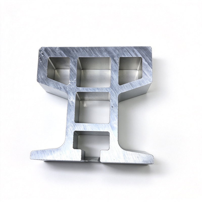
Custom Aluminum Profiles
RGV and AGV Rail Aluminum Profiles - Custom Extrusion
Extruded RGV/AGV guide rails with integrated wear face and guidance slot: straightness 1.0-1.5 mm over 10 m, hard anodized, bent to 0.5 deg.
Product Details
Short answer: an RGV or AGV rail is a beam with a wear face, and the number that decides whether the vehicle tracks is straightness accumulated over the whole run — not straightness per metre. We hold 1.0–1.5 mm over 10 m depending on load class, put the guidance slot and the rack or magnetic-strip channel into the same section, hard anodise only the running face, and bend curved sections to 0.5° of arc. The value on your order is set by your drawing, and we confirm the achievable straightness before the die is cut.
Why a rail is a different problem from a frame
A frame holds something still. A rail lets something move along it, repeatedly, for years, and the tolerance that matters is not the shape of one length — it is the path the vehicle actually follows. Three consequences follow, and they are the reason rails are specified differently from structural profiles.
- Straightness accumulates. Every length you bolt down adds its own deviation to the one before, and the vehicle sees the sum. A rail that is straight within 0.3 mm over its own 6 m but is jointed with a 0.2 mm step will produce a bump at every joint, once per pass, forever.
- The wear face is a bearing surface. The wheel or the roller runs on it. Surface hardness, flatness and roughness decide how long the rail lasts and how much the vehicle vibrates, which is why the running face is hard anodised and the rest of the section is not.
- The section carries guidance as well as load. A rail usually has to do three things at once: carry vertical load, resist lateral force from the guidance, and host the position reference — a rack, a magnetic strip, or a code band. Integrating all three into one section is what removes assembly error.
Straightness: the spec that is usually written wrong
"Straight within 0.5 mm" is not a specification. Straight over what length, measured how, in which plane? A rail can be straight in plan and bowed in elevation, and the vehicle feels both.
The three measurements that matter are: straightness of the running face in the vertical plane over the full installed length; straightness in the horizontal plane, which sets lateral tracking; and twist, which is what makes a four-wheel carriage rock. Twist is the one most often left off the drawing and the one that causes the most complaints, because a twisted rail cannot be corrected by shimming at the supports.
The achievable numbers depend on the section, not only on the process. A tall thin section bends more under its own weight between supports than a deep one, and a rail that is straight on the bench will sag when it is only supported every 1.5 m. That is a support-spacing calculation, not a machining tolerance: the rail is a beam, and the deflection between supports follows the same fourth-power relationship as any other beam.
Specifications
| Item | Range and note |
|---|---|
| Load class | Light to 300 kg, medium to 500 kg, heavy 1,000 kg and above |
| Alloys | 6063-T5 light, 6061-T6 medium, 6005A-T6 / 6082-T6 heavy, 7075-T6 only where unwelded |
| Circumscribed circle | Up to 700 mm |
| Straightness, light rail | ≤ 1.0 mm over 10 m |
| Straightness, medium rail | ≤ 1.2 mm over 10 m |
| Straightness, heavy rail | ≤ 1.5 mm over 10 m |
| Curved section accuracy | ≤ 0.5° of arc, CNC stretch-bent |
| Section tolerance | ±0.02–0.04 mm on critical dimensions |
| Running-face treatment | Hard anodising, 25–50 µm, ≥ 350 HV on the wear face only |
| Position repeatability, system level | Around 3 mm with an integrated magnetic-strip or code band, application dependent |
| Operating speed | Up to about 2.5 m/s; above that, rail joint quality dominates |
| Integrated features | Wear face, side guide, rack channel, magnetic-strip slot, cable tray, mounting holes |
| Maximum length | 6,500 mm per piece; longer runs are jointed with a machined splice |
| Reference standard | GB/T 6892-2023 high-precision grade |
Section design: what goes into the profile
The value of an extruded rail is that the guidance, the load path and the position reference all come out of one die. Every feature moved into the section is an assembly tolerance removed.
| Function | How it is made part of the section | Why it matters |
|---|---|---|
| Load carrying | Box or I-form core, depth set by support spacing | Deflection between supports is the real limit, not the material |
| Wear face | Flat land, machined or drawn, wide enough for the roller | Hard anodised and ground; roughness sets vibration and life |
| Lateral guidance | Side ribs or a channel with a machined reference face | Removes the need for a separate guide rail and its alignment |
| Position reference | Slot for a magnetic strip, code band or rack | Keeps the reference and the running face in one part, one tolerance |
| Mounting | T-slot or through-holes on a fixed pitch | Allows adjustment at installation without redrilling on site |
| Cable management | Side channel with a closable lip | Keeps the energy chain off the floor and out of the wheel path |
| Joint | Machined splice feature at each end | A joint with a step is a bump at every pass; a machined splice is not |
The joint is where a good rail fails
Two rails each within tolerance can still be jointed badly. What the vehicle experiences at a joint is a step, and a step of 0.1 mm at 2 m/s is an impulse the carriage feels as a knock. Three practices remove it.
First, joints are machined, not cut. A saw cut leaves a burr and a face that is not square to the running face; a machined end is square and can be butted. Second, the splice is dowelled rather than only bolted, because bolts in slotted holes allow a step. Third, the joint is aligned against the running face with a straight edge across the joint, not against the sides — a rail can be perfectly aligned on its flanks and still have a step on top.
Where the run is longer than a single length, the number of joints is a design decision worth taking seriously. Five joints in a 30 m run is a maintenance item; a continuous length is not. If the transport can take 12 m lengths, that is worth designing for.
Curved sections
Ring rails and curved runs are bent after extrusion, which introduces two constraints. The bend changes the section: the outside of the curve thins and the inside thickens, and a hollow section can ovalise if the bend radius is under roughly three times the section depth. And the bend relaxes, so the radius has to be over-bent and allowed to spring back, then checked.
The number that matters on a ring rail is not the radius, it is the accuracy of the arc — 0.5° of accumulated error over a full circle is a 3 mm gap at the closure joint. That is why ring rails are usually made as a matched pair from the same bend program rather than as two independently bent halves.
Where it does not fit
- Runs longer than 6.5 m in one piece. The rail is jointed, and joint quality becomes the limiting factor rather than rail quality.
- Loads that put the rail into plastic deformation. A rail is designed to stay elastic; if a vehicle can overload it, a steel rail with a hardened head is the right choice.
- Very high speed with tight positioning. Above a few metres per second, an aluminium extrusion with a jointed run is limited by the joints, and a machined steel or linear-guide system is the correct answer.
- Wash-down or food-contact environments where the anodic film will be attacked by caustic cleaners.
- Single-unit installations where a die cannot be justified. Stock rail plus a machined guide is cheaper and faster.
What to send for a quote
- The rail section drawing, with the running face and the guidance reference marked
- The vehicle load, the wheel arrangement and the support spacing, so deflection can be checked rather than assumed
- The total run length and the maximum transportable length, which sets the number of joints
- The straightness you need and over what length, and whether twist is specified
- The guidance and positioning method — mechanical guide, magnetic strip, code band, rack
- The surface treatment, and which faces are wear faces
- Whether curved sections are needed, with the radius and the arc tolerance
- Volume and the number of variants, since one section usually serves several vehicle sizes
FAQ
What straightness can you hold on a rail?
Reference 1.0 mm over 10 m for a light rail, 1.2 mm for medium and 1.5 mm for heavy. The value on your order is set by your drawing, and we confirm it in writing before tooling. Ask yourself first whether you need straightness of the section or of the installed run — the installed number includes the joints and the support spacing, and the section alone cannot deliver it.
Why is straightness specified over 10 m and not per metre?
Because a rail is a continuous path, not a set of independent parts. A section that is straight within 0.1 mm in any one metre can still accumulate 1 mm of bow over 10 m if the deviation is systematic, and that is what the vehicle follows. Specifying per metre lets a supplier pass a rail that will not track. Specify the accumulated value over the installed length.
Should the whole rail be hard anodised or only the running face?
Only the running face, in most cases. Hard anodising at 25–50 µm gives the wear resistance the wheel needs, but it is brittle, it changes the dimension by half the film per face, and it is an electrical insulator — which matters if the rail is also the earth path or part of a positioning system. Mask the rest, and specify the film thickness on the face that actually wears.
Can the guidance slot and the magnetic strip be integrated?
Yes, and that is the main argument for an extruded rail rather than a machined one. A slot for a magnetic strip or a code band produced by the die is in the same tolerance chain as the running face, so the reference and the path cannot drift apart. If the slot is machined afterwards, it is a second operation with its own fixture and its own error.
How are long runs jointed?
With a machined end face, a dowel for location and a splice plate, aligned against a straight edge across the running face. The joint is machined rather than sawn because a sawn face is not square to the running face and leaves a burr. Where the run is long, the number of joints is worth minimising at design stage — it is a permanent maintenance item.
Do you supply curved sections as well?
Yes, stretch-bent to 0.5° of arc, from the same section as the straight rail so the vehicle sees one profile throughout. Ring rails are made as a matched set from one bend program, because two halves bent independently will not close. Send the radius, the arc and the closure tolerance, and note that a bend radius below about three times the section depth will ovalise a hollow section.
Send your drawing
Email linjunbing@truetrustlv.com with the rail section, the vehicle load and the run length. If the section is not settled, send the wheel arrangement and the guidance method, and we will propose a profile that carries the load and hosts the reference rather than quoting a shape that will not track. You will get a section proposal, a joint and bending plan, and a price — reviewed by an engineer.
WhatsApp: +86 136 6644 0600
GET A QUOTE
Once you have submitted your requirements, we will contact you as soon as possible regarding your product inquiry.:RGV and AGV Rail Aluminum Profiles - Custom Extrusion