
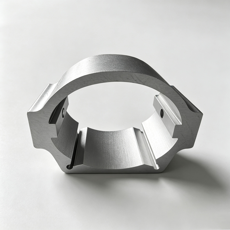
Custom Aluminum Profiles
EV Battery Tray Aluminum Profiles - Extrusion and FSW
Aluminum extrusions for EV battery trays, crash beams and motor housings: 6061/6005A/6082, ±0.03 mm, friction stir welded and sealed.
Product Details
Short answer: a battery-electric vehicle gives an aluminium extrusion four jobs — carry a 400–700 kg pack, keep water out of it, absorb crash energy without letting the cells see it, and do all of that at a weight the range can afford. Those four requirements pull in different directions, which is why the tray is usually an extruded multi-cell floor joined by friction stir welding. We extrude in 6061-T6, 6005A-T6, 6082-T6 and 6063-T5 up to a 700 mm circumscribed circle, hold key positions to ±0.03 mm, and confirm the achievable tolerance against your drawing before tooling.
Why an extrusion, and not a stamping or a casting
A battery tray is essentially a flat, sealed box with a structural floor. The three ways to make one are stamped steel, cast aluminium, and extruded aluminium joined by welding. Extrusion wins on three counts that matter more than raw material price.
The first is the section itself. A single extruded floor plank can carry four to eight closed cells across its width. Those cells are the crash structure: in a side impact or a bottom strike, the walls crush progressively and absorb energy, and the cell arrangement is designed to do exactly that. A stamping has to develop the same energy absorption through ribs that are welded on, and every welded rib is a heat-affected zone in a fatigue-loaded floor.
The second is that length is free. A tray die produces a continuous plank, cut to whatever length the pack needs. A different pack length is a saw setting and a new weld program, not a new tool.
The third is flatness. A tray floor has to be flat enough for the module mounting and, on a sealed design, flat enough for the cover gasket to seal against. Extruded plank is straighter and flatter than a large stamping, and it holds that flatness after welding better because the heat input is local.
Friction stir welding is not a preference, it is a consequence
Aluminium 6xxx loses roughly half its strength in the heat-affected zone of a fusion weld, and a battery tray is a long continuous seam where distortion compounds along the length. Friction stir welding solves both: it stirs the material in the solid state at around 450–500 °C, well below melting, so the joint retains a far higher fraction of parent strength and the distortion is a fraction of MIG.
What that means in practice: a tray floor joined by FSW holds its flatness without a straightening operation, and the seam is leak-tight without a sealant in most designs. MIG is still used where geometry prevents a stir tool from reaching — corners, upstands, closed box sections — and those seams then need a sealant and a distortion allowance. The design rule is to put the long straight seams within reach of the FSW head and keep MIG for the details.
The secondary benefit is that FSW leaves no filler metal and no porosity, so a helium leak test on a finished tray is far more likely to pass first time. That is where the cost of a fusion-welded tray actually shows up: not in the welding, but in rework and leak testing.
Specifications
| Item | Range and note |
|---|---|
| Alloys | 6061-T6 general structure, 6005A-T6 tray floor, 6082-T6 longitudinal members, 6063-T5 frames and covers |
| Circumscribed circle | Up to 700 mm |
| Wall thickness | 1.5–8 mm typical on tray plank; multi-cell floor from 2 mm |
| Extruded tolerance | ±0.02–0.04 mm on critical dimensions |
| Key assembly tolerance | ≤ ±0.03 mm, per drawing |
| Machined tolerance | ±0.01 mm typical |
| Maximum length | 6,500 mm machined; tray plank cut to pack length |
| Joining | Friction stir welding, MIG/TIG, structural adhesive, self-piercing rivets |
| Sealing | FSW seam plus gasket face; helium leak test available on request |
| Surface | Anodised, powder coated, electrophoretic coat, or conversion coated for bonding |
| Inspection | CMM report, material certificate, weld inspection record |
| Reference standard | GB/T 6892-2023; process documentation aligned to IATF 16949 flow-down |
| Trial quantity | From 50 kg for a development build |
| Location | Qingpu, Shanghai |
Which alloy for which part
| Component | Typical alloy | What governs the choice |
|---|---|---|
| Tray floor and PACK box | 6005A-T6 / 6061-T6 | Crush energy per kilogram, flatness, seal face quality after welding |
| Longitudinal member, sill beam | 6082-T6 / 6061-T6 | Bending and axial crush in a 40 % offset impact |
| Cross beam and bumper crash box | 6061-T6 / 7075-T6 | Peak load and stroke; 7075 only where it is not welded |
| Motor housing | 6061-T6 | Bore accuracy, thermal path, electromagnetic shielding continuity |
| Inverter and DC-DC frame | 6063-T5 | Mass, heat spreading, ease of machining |
| Cooling plate | 6063 high-conductivity / 3003 for brazed plate | Thermal conductivity and joinability to the coolant circuit |
| Cover and enclosure | 6063-T5 | Flatness, coating, EMI gasket land |
Sealing is a flatness problem before it is a gasket problem
A pack is specified to IP67 or IP6K9K, and the seal is at the cover joint. The gasket will tolerate a certain gap variation; what it will not tolerate is a joint face that waves. Weld distortion is the usual cause, and it is measured along the whole perimeter, not at one point.
The sequence that holds a seal face: machine the gasket land after welding, not before; keep the land at least 12 mm wide so the gasket has somewhere to sit; put the FSW seam away from the land; and avoid a machined land that crosses a weld toe. If the land must cross a weld, the land is machined after welding and the toe is dressed.
The second half of sealing is drainage and venting. A tray that can hold water will hold water, and a service bay that finds a litre of condensate inside a pack is a warranty event. A drain path to a defined low point and a breathable vent with a membrane is a design decision, not an accessory, and it costs almost nothing at drawing stage.
Crash: where the material goes
In a side pole impact the load enters through the sill and has to be spread across the tray before it reaches the cells. Two things do the work: the number of closed cells in the floor plank, and the continuity of the load path from sill to tray to cross member.
More cells means more energy per millimetre of crush and a lower peak force, which is what protects the modules. But more cells also means more die complexity and a heavier floor. The usual compromise is a floor plank with four to six cells and a wall of 2–2.5 mm, tuned so the crush force stays under the module's allowable acceleration. That tuning is done on the section, before the die is cut — it is very expensive to discover after a sled test.
The load path is the part that gets forgotten. A tray that is strong in the floor but bolted to the sill at four points will tear at the bolts. The mounts need to be continuous with the longitudinal member, and the bolts need to land in a thickened boss rather than in a single wall.
Where it does not fit
- A pack that must be structurally integral to the vehicle body (cell-to-chassis). That is a different architecture with a different joining philosophy; an extruded tray is a bolted or bonded module, not a load-bearing body panel.
- Anything requiring a pressure vessel certification. A tray is sealed against water and dust, not designed as a pressure container.
- A one-off or very low-volume build. Tooling, weld programming and fixture cost dominate; a fabricated tray from stock sections is the rational answer.
- Parts that will be welded after anodising. The coating is destroyed in the heat-affected zone and the anodic film contaminates the weld.
- Very deep drawn shapes with compound curvature. Extrusion produces a constant section; deep drawing is a different process.
What to send for a quote
- The tray or pack assembly drawing, with the gasket land, mount positions and the cell modules shown
- The crash load case and the acceleration limit at the modules, if it has been defined
- The sealing specification and whether a leak test is required
- The alloys and tempers, or the duty if the alloys are still open
- The joining method for each seam — FSW, MIG, adhesive, rivet — and which seams are visible
- The coating, plus any area that must stay conductive for grounding or EMI continuity
- Volume per year, the number of pack variants, and whether they share a section
- The documentation you need for your PPAP or equivalent flow-down
FAQ
What tolerance can you hold on a battery tray?
Reference ±0.03 mm on key assembly positions and ±0.02–0.04 mm on extruded section dimensions, with machined features at ±0.01 mm. The value on your order is set by your drawing, and we confirm in writing what we can hold before tooling. On a tray, the tolerance that usually matters is not the section but the flatness of the gasket land after welding — that is a process and sequencing question, and it is worth specifying explicitly.
Why friction stir welding rather than MIG?
Because a 6xxx fusion weld loses roughly half its strength in the heat-affected zone and pulls the part out of flatness along a long seam, while FSW joins in the solid state with far less strength loss and far less distortion. On a tray floor that means the flatness survives without straightening and the seam is usually leak-tight without sealant. MIG stays for corners and details the stir tool cannot reach.
Can you supply the tray welded and leak tested?
We supply extruded and machined components, and welded assemblies where the drawing calls for them, with weld records and a dimensional report. Leak testing is normally done by the tier-one assembler against the pack specification because the test is on the finished pack, not the tray. If you need a helium test at tray level, say so at quotation stage so the fixture and the test port can be designed in.
Which alloy for a crash beam?
6061-T6 for a welded or bolted beam, 6082-T6 where higher strength is needed and the part is not welded, and 7075-T6 only where the beam is a machined or bolted part with no welding at all — 7075 is effectively unweldable in production and is sensitive to stress corrosion cracking in the short-transverse direction. The energy absorption comes from the section geometry, not from the alloy, so the section is designed first and the alloy chosen to suit the joining method.
Do you anodise or coat the tray?
Either, and often neither is right for the whole part. Powder coat or electrophoretic coat is common on covers and visible structure; a conversion coating is common where the tray is bonded or where a gasket sits; anodising is common where wear or corrosion resistance is needed on a bare surface. Any area that has to carry earth or EMI continuity must be masked, because an anodic film is an insulator.
What volume makes tooling worthwhile?
A development build starts at 50 kg, which is enough to prove a section and a weld program. Tooling pays back when a section is shared across pack variants or carried into a second model year — that reuse, not the unit price, is where the extrusion beats a fabrication. If the pack is a one-off, we will say so and quote a fabricated alternative.
Send your drawing
Email linjunbing@truetrustlv.com with the tray drawing, the crash load case and the sealing specification. If the section is not settled, send the pack envelope and the module layout, and we will propose a floor plank and a joining plan rather than quote a shape that will not seal. You will get a section proposal, a weld and coating sequence, and a price — reviewed by an engineer.
WhatsApp: +86 136 6644 0600
GET A QUOTE
Once you have submitted your requirements, we will contact you as soon as possible regarding your product inquiry.:EV Battery Tray Aluminum Profiles - Extrusion and FSW