
Automated logistics
Heavy-Load RGV Track - Fixings and Anchors
A heavy rail fails at the fixings, not in the section. Bolt detail in thin aluminium walls, anchor edge distance, and the four-stage failure sequence.
Product Details
A heavy-load RGV track fails at the fixings far more often than in the section. The profile can be sized correctly, machined correctly and anodised correctly, and the installation will still move if the anchors are wrong — because the anchor is the only part of the system that has to hold in two different materials at once.
The main heavy-load rail page deals with what happens at the running surface, where wheel pressure yields the flange. This page follows the load the rest of the way down: through the rail's fixing detail, into the anchor, and into the concrete.
Where the load actually goes
A 1000 kg vehicle on four wheels delivers around 2.5 kN per wheel statically. With a dynamic factor for travel and braking, the design wheel load is 3.3 to 3.8 kN. That load enters the running flange, spreads through the web, and reaches the mounting face at the base of the section.
From there it goes into whatever fixing detail the section provides — a T-slot, a drilled hole, a clamped plate — and then into an anchor in the floor. Each of those transitions is a place where capacity is lost, and the losses are not small. A well-designed rail on a badly chosen anchor has less capacity than a modest rail on a good one.
The reason this is worth stating plainly is that section catalogues quote bending capacity, and bending capacity is almost never the governing case on a floor rail. The rail is short-span and heavily supported; the fixings are where the stress concentration and the material change are.
Specifications
| Item | Reference value | Notes |
|---|---|---|
| Alloy and temper | 6061-T6, yield ≥ 240 MPa | Higher hardness at the running face than 6063 |
| Vehicle class | 500–1000 kg | Also used for stacker crane floor rails |
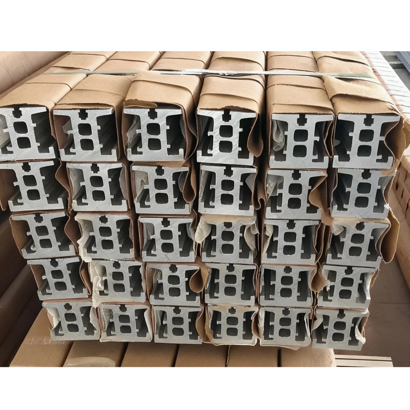
| Section example | 200 × 100 mm heavy section | Thickened walls at the running flange |
| Straightness | Reference ≤ 1.5 mm over 10 m | Measured on the running face |
| Dual-rail parallelism | Reference ≤ ±0.8 mm over 10 m | Set at installation as well as at machining |
| Machined tolerance | Reference ±0.02 to ±0.04 mm | Mounting faces and guide grooves |
| Travel speed | Up to 2.5 m/s | Impact at joints rises with speed squared |
| Positioning | Reference ≤ ±3 mm | System figure, drive and encoder included |
Reference values come from shipped projects. The value on your order is set by your drawing, and we confirm the achievable tolerance and the fixing detail in writing before you order.
Bolting into a thin aluminium wall is the first trap
Aluminium has no fatigue-free thread engagement in thin walls, and a heavy RGV track is a vibrating structure. A bolt threaded directly into a 4 mm wall will pull out long before the rail itself is stressed — the thread strips or the flange tears at the hole.
There are three fixing details that work, in order of preference:
- An extruded T-slot with a T-nut or hammer-head bolt. The load is spread along the slot rather than at a point, and the slot wall is in shear rather than tension. This is the detail to design in at the extrusion stage; it cannot be added later.
- A through-bolt with a backing plate. The bolt passes through the section and clamps against a plate on the far side, so the aluminium sees bearing and compression rather than a pull-out load. Works on any section, but needs access to the far side.
- A drilled and tapped hole with a thread insert. A stainless or steel insert gives a proper thread in the aluminium, and the insert's pull-out capacity is predictable. Suitable where a T-slot is not available.
What does not work on a heavy track is a self-tapping screw or a direct thread in a wall under about 6 mm. It will hold at commissioning and it will not hold after a year of vibration.
Anchors into concrete: three numbers decide the capacity
Once the load is in the rail's fixing detail, it has to get into the floor. For a mechanical or chemical anchor in concrete, the capacity is governed by three things, and none of them is the anchor's catalogue tension value:
- Edge distance. An anchor close to a slab edge or a joint fails by breaking out a cone of concrete rather than by pulling out. The minimum edge distance for a typical M12 anchor is around 60 to 100 mm depending on the type, and a rail laid 40 mm from a slab joint is a problem regardless of the anchor.
- Concrete strength and condition. Capacity scales with the square root of compressive strength. More importantly, a cracked section of slab behaves very differently from an uncracked one, which is why cracked-concrete-approved anchors exist and why they should be used wherever the slab may crack under the rail.
- Slab thickness and reinforcement. A thin slab on grade with no mesh will break out at a lower load than the anchor's rating suggests, because the failure cone has nowhere to develop.
A practical rule we work to: if the rail run crosses a slab joint, treat the anchors within 300 mm of the joint as being in cracked concrete and specify accordingly.
Anchor pitch is a continuity decision
Heavy RGV rails are usually fixed at 500 to 800 mm. Choosing within that range is not about strength — the rail is far stiffer than the anchors need — it is about continuity and about movement.
A continuous rail on a rigid line of anchors behaves as a continuous beam, so a local settlement at one anchor redistributes rather than creating a step. A rail with sparse anchors behaves as a series of simply supported spans, and one soft anchor becomes a dip that the vehicle feels twice per pass.
At the same time, a continuous line of anchors restrains thermal movement completely. A 20 m aluminium rail grows about 5 mm over a 10 °C swing, and if every anchor is a hard clamp, that movement goes into the rail as compression and into the anchors as shear. The usual solution is to clamp firmly at one point and use slotted holes or a sliding washer elsewhere, so the rail can move along its axis while staying located across it.
What fails first in service
The failure sequence on a heavy floor rail is consistent and slow:
- Anchor relaxation. Concrete creeps under sustained preload, and the anchor loses a fraction of its tension over the first year. Nothing visible happens, but the rail is now resting rather than clamped.
- Fretting at the fixing. A rail that is resting rather than clamped moves a few micrometres under every wheel pass. That movement polishes the aluminium under the washer and eventually opens a gap.
- Hole elongation. Once there is a gap, the bolt sees shear reversal and the hole in the aluminium becomes oval. The oval grows faster than the wear that started it.
- Visible movement. By the time the vehicle operator notices a click or a shift, the holes are already damaged and the fix is a repair, not a re-torque.
The countermeasure is a re-torque at six months and a check of the hole condition at the same visit. It costs one shift and it resets the clock.
Where it does not fit
Four cases where this rail, or this fixing approach, is wrong. If the slab is a suspended structural slab rather than on grade, the slab's own deflection under a moving load will exceed anything the rail does, and the slab has to be assessed before the rail is designed. If the rail has to run over an expansion joint in the building, a continuous aluminium rail cannot follow it and the joint needs a purpose-made crossing detail. If the vehicle load is above about two tonnes per wheel, a steel rail with a hardened running strip is the more durable answer. And if the floor is coated with a soft resin system, the coating has to be cut away at each anchor — an anchor that bears on coating rather than concrete has almost no capacity.
What to send for a quote
- The vehicle weight, wheel count and wheel load, plus the travel speed and braking rate.
- The floor drawing with slab joints, edges and thickness, and the concrete specification if it is known.
- The section drawing or the fixing detail you intend to use — T-slot, through-bolt or insert.
- Whether the rail crosses any slab joints, and whether the run is long enough to need an expansion allowance.
Send those and we can propose a fixing pattern with the load at each anchor, which is the drawing the civil or structural engineer needs to check.
FAQ
What tolerance can you hold on a heavy track?
Reference ±0.02 to ±0.04 mm on machined faces and guide grooves, with 1.5 mm over 10 m straightness and ±0.8 mm over 10 m parallelism between rails. The ±3 mm positioning figure is a system result that includes the drive and encoder. The value on your order is set by your drawing, and we confirm the achievable machined tolerance in writing before you order.
Can I drill and tap the rail on site?
You can, but the hole will have no corrosion protection and the thread will be in bare aluminium. If site drilling is unavoidable, use a thread insert and touch up with a suitable coating. It is much better to have the holes machined and the rail anodised around them.
How deep does the concrete need to be?
As a guide, at least twice the anchor's effective embedment depth, plus reinforcement. For a typical M12 chemical anchor with 110 mm embedment, a 200 mm slab with mesh is a reasonable minimum. Thinner slabs need a through-bolt or a cast-in channel.
Why do my anchors come loose?
Concrete creep under sustained preload, and vibration. Re-torque once at six months, then annually. If they come loose again after that, the anchor type is wrong for the slab condition — usually a standard anchor in what is effectively cracked concrete.
Should the rail be clamped at every anchor?
No. Clamp firmly at one point per run and allow sliding elsewhere, or the thermal movement becomes compression in the rail and shear in the anchors. A slotted hole with a hardened washer is the usual detail.
Does hard anodising help at the fixings?
It helps against corrosion but it does not add pull-out strength, and it is brittle in a bearing situation. Where a bolt clamps directly onto an anodised surface, the coating will crack under the washer. Mask the fixing areas or use a plain washer large enough to spread the load.
Next step
Send the vehicle data and the floor drawing. We will come back with a section, a fixing detail and an anchor pattern with the load at each point, so the floor can be checked before the rail is made.
Email: linjunbing@truetrustlv.com | Call or WhatsApp: +86 136 6644 0600
GET A QUOTE
Once you have submitted your requirements, we will contact you as soon as possible regarding your product inquiry.:Heavy-Load RGV Track - Fixings and Anchors