
Automated logistics
Climbing Robot Rail - Anchoring and Torsion
A vertical climbing rail fails at its anchors and in torsion, not in bending. Joint steps, section shape, and why a rack cannot be anodised.
Product Details
A horizontal rail carries a load downward and a horizontal rail's design case is bending. A vertical climbing rail carries a load sideways, and its design case is something else entirely: the load acts at a distance from the rail face, the anchor has to hold the whole assembly up, and the rail itself has to resist being twisted about its own axis by a robot whose centre of gravity does not sit on the rail line.
That is why a climbing rail that passes a bending check can still develop a wobble at the third mast section, wear its guide wheels on one side, and loosen its anchors within a year. The numbers that matter are the anchor pull-out, the torsional stiffness of the section, and the alignment of the joints between vertical segments.
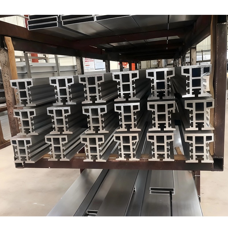
We extrude and machine climbing and travel rail sections in 6063-T5 and 6061-T6, with straightness of 1.0 mm per 10 m, dimensional tolerance of ±0.02 to ±0.04 mm, integrated guide slots and sensor grooves, and a hard anodised running surface for the high-cycle contact of a climbing wheel.
The four ways a climbing rail fails
| Failure | What causes it | What the operator sees | What controls it |
|---|---|---|---|
| Anchor pull-out | The rail carries the whole robot and payload vertically, plus a moment from the offset load | Loosening anchors, movement at the base, cracking in the host structure | Anchor design with a pull-out test, edge distances, and a safety factor appropriate to the duty |
| Torsion / lateral bow | Robot centre of gravity offset from the rail face; guide wheel preload on one side | Wobble during ascent, uneven wheel wear, binding at speed | A section with torsional stiffness, two-plane guidance, and preload controlled by design rather than by adjustment |
| Running surface wear | High-cycle contact between a wheel or pinion and the rail face | Play develops, positioning accuracy falls, debris in the aisle | Hard anodising on the running face, or a steel wear strip where the contact stress is high |
| Joint misalignment | Segments stacked and joined on site, each joint a possible step | A bump at every mast joint, worse at speed | Matched machined ends, a locating feature, and a stated joint step tolerance |
Three of those four are not bending problems, and none of them is solved by making the section thicker. They are solved by the section's shape, the way it is anchored, and the way the segments are joined.
Anchoring: the rail hangs the robot, so the anchor is the structure
On a horizontal rail the fasteners mostly hold the rail down against its own load and the trolley's. On a vertical rail the fasteners hold everything up, and they do it with the load applied at an offset, which adds a moment to the shear. The anchor is therefore a tension-and-shear connection, and it is the part of the design most often left to the installer.
What a customer should require, and what is often missing from the drawing:
- A stated anchor type and size, appropriate to the host material — concrete, steel column, or the racking upright. An anchor chosen for concrete used in a thin steel section, or the reverse, will not carry the calculated load.
- Edge distances and spacing respected. A chemical anchor close to the edge of a slab fails at a fraction of its catalogue capacity, because the failure is a concrete cone rather than the anchor itself.
- A pull-out test on the first anchors on site. It is a five-minute test and it is the only way to know that the host material is what the drawings assumed.
- A safety factor that reflects the duty. Where the rail is a fall-protection element or the machine operates near people, the factor is set by the applicable standard, not by the supplier's preference.
One structural note worth passing on: an aluminium rail on a steel rack is a galvanic couple, and a wet or humid environment will corrode the aluminium at the contact. Isolating washers or a coated interface cost very little at installation and prevent a slow loss of preload that is invisible until an anchor is inspected.
Torsion is the reason the section shape matters more than its size
A robot climbing a rail hangs its mass on one side of the rail face and its wheels press on the other. The offset between the wheel contact and the robot's centre of gravity produces a moment about the rail axis, and an open section — which a climbing rail almost always is, because it needs a guide slot and a mounting face — is weak in torsion.
The torsional stiffness of an open thin-walled section is governed by the wall thickness cubed, summed over the developed length. Doubling the wall thickness multiplies torsional stiffness by eight; adding depth to the section without closing the loop adds almost nothing. That is the counter-intuitive part: a deeper, heavier open section can be barely stiffer in torsion than a shallow one, while a closed shape of the same weight can be an order of magnitude stiffer.
Where a climbing rail has to be open, the practical answers are:
- Two-plane guidance — wheels bearing on two opposed faces, so the robot's offset moment is reacted as a couple rather than as a torque on the section.
- The guide feature placed on the section's neutral axis where the layout allows, so the load eccentricity is small.
- Local reinforcement at the anchor points, which is where the torsion enters the rail from the building.
Straightness of 1.0 mm in 10 m is a joint requirement, not a rolling requirement
A straightness figure quoted per 10 m is a useful number for the profile, but on a 12 m climb the alignment the robot actually experiences is set by how the segments line up. Two perfectly straight 6 m lengths can be joined with a 0.5 mm step, and the robot will feel that step twice per cycle for the life of the installation.
So the drawing should carry two separate requirements:
| Requirement | Reference value | Why it is separate |
|---|---|---|
| Straightness along a single piece | ≤ 1.0 mm per 10 m | A property of the extrusion and the straightening after extrusion |
| Joint step at the running face | 0.05–0.1 mm, with matched machined ends | A property of the machining and the assembly, and what the robot feels |
| Verticality of the assembled mast | Set by the anchor layout and shimming | A property of the installation, not of the rail |
| Cumulative deviation over the full height | Stated as a total, not a rate | Rates multiply; a 12 m mast at 1.0 mm per 10 m is 1.2 mm, not zero |
The cheapest way to meet a joint step requirement is to machine the mating ends as a pair and provide a locating feature — a spigot, a dowel or a tongue-and-groove — so the alignment is built into the parts. Leaving it to the installer with a straight edge and a torque wrench produces a different result on every mast.
The drive interface decides the surface treatment
A climbing robot drives either on a friction wheel or on a rack. The two put completely different demands on the rail:
Friction drive needs a hard, consistent, clean surface with a predictable coefficient of friction. Hard anodising is the usual answer: a coating in the 400–500 HV range on the running face, applied after all machining, with the growth of about 25 µm per surface allowed for in the dimension.
Rack drive puts the wear on the rack teeth, not on the rail face, and the rack cannot be anodised usefully — a coating on a tooth form changes the pitch line and chips at the tooth tips under load. Rack teeth are best extruded to shape and left bare, or protected by a steel rack bolted to the aluminium section.
Either way, the surface treatment has a sequence requirement: it comes after bending and machining, never before. A coated rail that is then drilled or cut leaves bare metal at every opening, and a coated rail that is then bent cracks the coating exactly where the wheel runs.
What the integration is worth
A climbing rail usually has to carry, on one section: a guide slot for the wheels, a mounting face for the rack or the drive, a sensor groove for the position reader, a cable channel, and the anchor bolt line. Extruding all of it into one section removes several metres of machining per metre of rail, and it also fixes the relationship between the guide slot and the rack pitch — which is the dimension a machined assembly struggles to hold.
Fatigue on a climbing rail is a wheel-pass count
A robot climbing 12 m and returning is a cycle, and a busy sorting system runs thousands of cycles a day. Over ten years that is a cycle count in the millions, and aluminium has no endurance limit — the S-N curve keeps falling, so the design has to be made against a count rather than against a single load.
Two details dominate: the joint, where a step produces an impact on every pass, and the anchor region, where the load enters the section through a bolt hole that is a stress raiser. A generous transition, a smooth running face and a preloaded anchor connection do more for the life of the rail than a thicker wall does.
Specifications
| Item | Reference value |
|---|---|
| Alloys | 6063-T5, 6061-T6 |
| Straightness | ≤ 1.0 mm per 10 m |
| Dimensional tolerance | ±0.02 to ±0.04 mm |
| Joint step at the running face | 0.05–0.1 mm with matched machined ends |
| Maximum length per piece | 6,500 mm; longer masts assembled from matched segments |
| Typical installation height | Up to 12 m of vertical travel, assembled from segments |
| Integrated features | Guide slot, rack seat, sensor groove, cable channel, anchor bolt line |
| Running surface | Hard anodised for friction drive; bare or steel rack for rack drive |
| Coating growth | About 25 µm per surface at 50 µm coating thickness |
| Inspection | Dimensional report, straightness, joint step, coating thickness |
| Standard | GB/T 6892-2023 high precision grade |
Where it does not fit
- Very high contact stress at the wheel or pinion. Hard anodising resists wear but is brittle; above roughly 3 kN on a small wheel the coating cracks and spalls. A steel wear strip or a steel rack carries that load, with the aluminium doing the structural job.
- Outdoor masts with wind loading. The rail is then a slender structure in bending and the calculation changes completely; we supply the section and the properties, and the structural verification belongs to the machine designer.
- Fall-protection applications where the rail is the anchor. That is a certified safety component with its own standards, testing and traceability, and it should be sourced as one rather than assembled from a structural profile.
- Heights beyond the transport and assembly limit. A 12 m mast is assembled from segments with matched joints; a 30 m one needs a different structural concept, not more segments.
- Racks that must be anodised. A coating on a tooth form changes the pitch line and chips at the tips. Use a bare extruded rack or a steel rack.
FAQ
What straightness and tolerance can you hold?
Reference straightness of 1.0 mm per 10 m, dimensional tolerance of ±0.02 to ±0.04 mm, and a joint step of 0.05–0.1 mm where the ends are machined as a matched pair, in lengths up to 6,500 mm. Those are capability references: the value on your order is set by your drawing, and the achievable straightness depends on the section and its handling. We confirm the achievable figures in writing before the die is cut.
Why does my climbing robot wobble as it goes up?
Two likely causes, and they are different. If the wobble grows with height, it is the assembled mast: verticality and joint alignment, not the profile. If it is present at every height and worse at speed, it is torsion — the robot's centre of gravity is offset from the rail face and the open section is rotating under the resulting moment. Two-plane guidance fixes the second; shimming and matched joints fix the first.
How is the rail fixed to the racking?
Through a bolt line extruded into the section, with anchors sized for the host material and the calculated tension and shear. The drawing should state the anchor type, the edge distances and the pull-out requirement, because the connection carries the entire robot vertically and the failure mode is in the host structure rather than in the rail.
Friction drive or rack drive?
Rack drive if positioning accuracy and payload matter: no slip, a defined pitch, and predictable positioning. Friction drive if the system is simpler and lighter, at the cost of a hard anodised surface, sensitivity to contamination, and some slip under acceleration. The rail section is different for the two, so it has to be decided before the die.
Can the rail be anodised in a colour?
The running face is usually hard anodised in its natural dark grey, because a dyed hard coating is not standard. Decorative faces can be anodised or powder coated, but any coating on the running surface changes the fit and has to be accounted for in the slot dimension.
What is the maximum height?
We supply segments up to 6,500 mm with matched machined ends; the assembly height is limited by the structure and by how the joints are aligned. Installations around 12 m of travel are common. Beyond that the mast becomes a slender structure in its own right and needs an engineering check rather than a longer rail.
Send your drawing
Email the section drawing with the robot mass and centre of gravity, the drive type, the travel height and the anchor detail to linjunbing@truetrustlv.com, or send it on WhatsApp at +86 136 6644 0600. You will get a note on the torsional and anchoring requirements, the achievable straightness and joint step, and a written tolerance statement.
GET A QUOTE
Once you have submitted your requirements, we will contact you as soon as possible regarding your product inquiry.:Climbing Robot Rail - Anchoring and Torsion