
Automated logistics
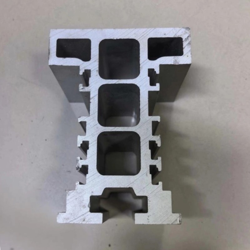
AGV Magnetic-Stripe Navigation Guide Rail Aluminum Profile
AGV magnetic guide rails in 6063-T5 with a machined tape slot, straightness 1.0 mm over 10 m, +/-0.02-0.04 mm. Slot and section per your drawing.
Product Details
Short answer: an AGV magnetic-stripe guide rail is an aluminum profile with a slot formed into the section that holds the navigation tape at a fixed height and a fixed line position. The slot is the product: its width and depth decide whether the tape sits flat, whether it can be replaced, and whether the vehicle's sensor sees a clean field. Working reference: straightness within 1.0 mm over 10 m, machined features at ±0.02–0.04 mm. Slot dimensions and section are set by your drawing.
What it is used for
It guides AGV and AMR fleets on a fixed route: 3C electronics assembly lines, automotive component plants, pharmaceutical and food production, warehouse transfer routes, hospital and laboratory logistics, and any site where vehicles repeat a path many times a day.
The rail does two jobs at once. It carries the navigation tape in a protected slot instead of laying it on the floor, and it gives the vehicle a defined running surface so the sensor stays at a constant height above the tape. Both matter, and the second one is usually underestimated.
It also serves as the physical reference for the route. Vehicles follow the tape, but the tape follows the rail, so the route accuracy is really the rail accuracy plus the installation accuracy. That is why the rail is machined rather than simply extruded and cut.
Specifications
| Item | Working reference | How it is set |
|---|---|---|
| Alloy | 6063-T5 | Chosen against your vehicle load |
| Straightness | ≤1.0 mm over 10 m | Set by your drawing |
| Machined tolerance | ±0.02–0.04 mm | Set by your drawing |
| Tape slot | Formed in the section, machined where the fit matters | Set by your tape width and thickness |
| Running surface | Machined flat, burr-free | Set by your vehicle wheel |
| Curve radius | Down to 1000 mm on bent sections | Set by your layout |
| Surface | Anodized, with the slot interior finished | Set by your environment |
| Machining | Slot machining, drilling, end machining, deburr | Per your drawing |
How it is made
- The section is extruded with the tape slot formed in the die, then the slot is machined where the fit to the tape matters.
- The running surface is milled flat, because the sensor height is referenced to it and a wavy surface modulates the signal.
- Bent sections are roll bent and checked before the slot is finished, since bending moves the slot geometry.
- Holes and end features are machined on one datum along the length.
- Anodizing follows, with the slot interior finished so the tape slides in without tearing.
Where this fits
It fits when the route is stable, when the floor is not flat enough or not clean enough to lay tape directly, and when vehicles repeat the same path at a frequency where tape replacement would otherwise be a maintenance burden.
Where it does not fit: if the route changes often, tape in a slot is harder to re-route than tape on the floor, and a SLAM or QR-code system may suit better. If the vehicle is a heavy forklift class, the rail section and the floor anchors become a civil question rather than a profile question. And if the site is a cleanroom with strict particle limits, the tape itself and its adhesive have to be evaluated, not only the rail.
What the slot has to do, and why it is hard
The tape has to sit flat and stay flat. A magnetic tape in a loose slot buckles and lifts in the middle of a span, and the sensor sees a wandering field. A tape pinched too tightly is deformed, and a deformed tape has a weaker field at the edges. The slot width and depth therefore have a real tolerance window, and it is narrower than people expect: roughly the tape thickness plus a small clearance, with the depth set so the tape face sits at the height the sensor is calibrated for. This is why the slot is machined rather than left as-extruded, and why we ask for the tape specification rather than only the rail drawing.
Sensor height is a signal quality parameter. Magnetic sensors have a working range of a few centimetres, and the field strength falls with distance. If the rail surface is wavy, the vehicle pitches as it moves and the sensor height oscillates, which shows up as intermittent loss of the guide line rather than as a gradual degradation. A machined running surface and a straightness call of 1.0 mm over 10 m are what keep the vehicle level, and the straightness figure is really a statement about signal stability.
Iron and steel debris are the specific enemy. A magnetic guide system is disturbed by ferrous particles, and in a machining plant, a foundry or a welding shop those are everywhere. Tape laid on an open floor collects them and the route drifts. A slot with a lip, or a slot with a cover strip, keeps the tape out of the debris path and makes cleaning possible. This is the case where the rail is not just a mounting feature but a functional shield, and it is worth specifying the lip height deliberately.
Replacement has to be possible without dismantling the line. Tape wears, and it wears faster at curves and at stops where vehicles turn or brake. A slot that traps the tape, or that requires lifting the rail to replace it, turns a ten-minute job into a shutdown. The section should let the tape be pulled through and re-seated from the top, which is a design decision made at the die.
And the rail is a route record. Because the tape follows the rail, a rail installed slightly off the drawing line puts the whole route off, and vehicles will track it faithfully in the wrong place. Installation datum matters as much as machining tolerance here, and it cannot be corrected in the vehicle software without re-teaching every station.
What to send for a quote
- The rail section drawing with the slot dimensions
- The tape specification: width, thickness and adhesive type
- The vehicle's sensor type and its working height above the tape
- Route layout with straights, curves and the stopping positions
- Environment: metal dust, coolant mist, washdown or cleanroom
FAQ
What straightness and tolerance can you hold?
Straightness within 1.0 mm over 10 m and machined features at ±0.02–0.04 mm are our reference values on this family, with the tape slot machined to the fit your tape needs. The value on your order is set by your drawing, and we state the slot tolerance band explicitly because that is what decides whether the guide line is stable.
Why does the rail need a slot instead of laying tape on the floor?
Protection and repeatability. Tape on an open floor collects ferrous debris, gets driven over and lifts at the edges, and each of those disturbs the field the sensor reads. A slot holds the tape flat at a fixed height, keeps debris out and makes replacement a pull-through job instead of a shutdown.
Which navigation methods does the rail suit?
Magnetic tape is the main one, and the section can also carry a QR-code strip or a reflective band in a similar slot. Laser SLAM needs no guide at all, so a rail is only there to give a defined running surface. The choice is really about whether the route is fixed and whether the environment is dirty.
How tight should the slot be?
Tight enough that the tape cannot lift or shift, loose enough that it can be installed and replaced without distortion. That is a small window, and it depends on the tape: send the tape specification and we will set the slot from it rather than from a generic clearance.
What does the customer need to provide?
The section drawing or the vehicle interface, the tape specification, the sensor working height, and the route layout. From those we can define the slot, the running surface and the bend plan.
Can the rail be curved?
Yes, down to a 1000 mm radius on bent sections, with the slot checked after bending because bending distorts the slot geometry. A curve is also where tape wears fastest, so the slot lip and the surface finish matter more there.
Next step
Send the section drawing with the tape specification and the sensor height. We will come back with a slot definition, a running-surface plan and a tolerance statement against your drawing.
Email: linjunbing@truetrustlv.com | Call or WhatsApp: +86 136 6644 0600
GET A QUOTE
Once you have submitted your requirements, we will contact you as soon as possible regarding your product inquiry.:AGV Magnetic-Stripe Navigation Guide Rail Aluminum Profile