
Automated logistics
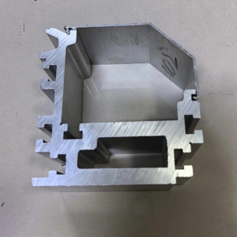
Robot Overhead Rail Aluminum Profile
Robot overhead rails in 6061-T6, straightness 1.0 mm over 10 m, splice gap 0.5 mm, +/-0.02-0.04 mm machined. Section per robot pose and drawing.
Product Details
Short answer: a robot overhead rail is the seventh axis: a linear track mounted above the work cell that carries a robot along a production line so one robot can serve several stations. Working reference: straightness within 1.0 mm over 10 m, machined features at ±0.02–0.04 mm, splice gap at or under 0.5 mm, arc error within ±0.4 mm on bent sections. Alloy and section are set by your drawing; the accuracy you actually need is set by the robot on top of it.
What it is used for
It goes into welding cells, painting and sealing lines, machine tending, palletizing, inspection stations and any cell where a single robot has to reach a line of positions rather than one fixed spot. It is also used for gantries where the robot hangs below the rail, and for inverted and wall-mounted arrangements.
The commercial reason is simple: a robot is expensive, and a rail lets one robot cover several stations in sequence instead of buying one robot per station. The technical cost is that everything the robot does now depends on a moving base, and the base is no longer a casting bolted to a floor.
Specifications
| Item | Working reference | How it is set |
|---|---|---|
| Alloy | 6061-T6 for robot travel, 6063-T5 for light lifting rails | Chosen against your robot and reach |
| Straightness | ≤1.0 mm over 10 m | Set by your drawing |
| Machined tolerance | ±0.02–0.04 mm | Set by your drawing |
| Splice gap | ≤0.5 mm between sections | Set by your acceptance method |
| Bent section accuracy | Ring error ±0.4 mm, curvature 0.5 degrees | Set by your drawing |
| Section range | Weight 0.05–100 kg/m, circumscribed circle 5–700 mm | Chosen against your load |
| Section shape | I-beam or H-beam, selected by the load direction | Chosen against the robot pose |
| Machining | Running faces, rack mounting, hanger points, end machining | Per your drawing |
How it is made
- The section is extruded to the customer's drawing, with the running geometry and the hanger interface formed in the die.
- The running faces are machined, because the carriage runs on them and a formed surface will not hold the straightness a precision axis needs.
- Holes, rack mounting and hanger points are machined on one datum along the length, so the rail and the rack stay aligned over the full travel.
- Joint faces are machined so the splice gap stays within 0.5 mm and the transition is flat in the running direction.
- Bent sections, where the layout needs them, are roll bent and checked against a template before the running faces are finished.
Where this fits
It fits when one robot has to serve several positions, when the cell height allows an overhead structure, and when the payload and reach are within what an aluminum section can carry without excessive deflection.
Where it does not fit: if the robot needs to work at only one station, the rail adds cost and a failure mode for nothing. If the reach is long and the payload heavy, the deflection at full extension may exceed what the process allows and a steel structure is the honest answer. And if the process tolerance is tighter than the rail can hold, buying a better rail is the wrong fix; the process needs a fixed station.
Three things that decide whether the cell works
Stiffness matters before accuracy does. A robot at full reach applies a bending moment and a torque to its base, and on a moving carriage that load goes into the rail rather than into a floor anchor. If the rail deflects, the robot's own accuracy is irrelevant, because the base has already moved. The section has to be chosen for the deflection at the worst pose, not for a nominal load in the middle. This is where a rail that looks adequate on a static calculation fails in a real cycle, and it is worse on an inverted robot, where the arm loads the rail in torsion as well as bending.
I-beam and H-beam are not interchangeable. An I-section puts material in the flanges and is efficient in bending about its strong axis, which suits a carriage loaded mainly vertically. An H-section is wider relative to its depth and is much better in torsion, which suits a robot that reaches sideways and twists the rail. Asking which is better without describing the robot's working envelope has no answer, and picking by appearance or by what was used on the last project is how a cell ends up with a rail that rings and vibrates at full reach.
The splice gap is a positioning error, not a cosmetic one. When the carriage crosses a joint, the wheels drop into any gap and climb out again. At 0.5 mm the drop is small enough that the carriage stays on its datum. Open it further and the carriage pitches slightly at every crossing, which moves the tool centre point, which moves the weld or the bead. A robot welding at a fixed station would never see this, because it never crosses a joint. On a seventh axis it happens on every pass, and the weld quality varies along the rail in a pattern that repeats at the same spacing as the joints.
And the datum is shared with the rack. The carriage position comes from a rack or a linear scale, and the rack has to be parallel to the running face over the whole travel. If the rail is straight and the rack is mounted from a different reference, the axis reads a position that the mechanics do not deliver. Machining both from one datum is the only way to keep them consistent, and it is the reason we machine rack mounting rather than leaving it to assembly.
What to send for a quote
- The rail section drawing, or the carriage and robot interface if the section is open
- Robot model, payload, reach and the working envelope, including the worst pose
- Travel length, speed and acceleration
- The accuracy the process needs at the tool, so the rail budget can be derived from it
- Mounting arrangement: floor, overhead, inverted or wall-mounted
FAQ
What straightness and tolerance can you hold?
Straightness within 1.0 mm over 10 m, machined features at ±0.02–0.04 mm, and a splice gap at or under 0.5 mm are our reference values on this family, with bent sections held to ±0.4 mm ring error and 0.5 degrees. The value on your order is set by your drawing, and the figure that matters most for a robot axis is the splice gap, so we state it separately.
How accurate does the rail need to be for my robot?
It should not consume the whole error budget. If the robot repeats to ±0.05 mm and the process allows ±0.5 mm at the tool, the rail can take part of that, but the deflection under load has to be counted first. Send the process tolerance and the worst robot pose, and the rail requirement follows from those rather than from a standard table.
I-beam or H-beam?
I-beam where the load is mainly vertical and bending dominates, which is the common case for a carriage running along a line. H-beam where the robot reaches sideways and applies torque, or where the rail is inverted and the arm twists the base. The choice follows the working envelope, and getting it wrong shows up as vibration at full reach.
Why is the splice gap limited to 0.5 mm?
Because the carriage crosses it every pass. A larger gap lets the wheels drop and climb, which pitches the carriage and moves the tool centre point. The result is a periodic error in the work that repeats at the joint spacing, which is hard to diagnose and easy to prevent.
Can the rail be curved or form a ring?
Yes, with roll-bent sections held to ±0.4 mm ring error and 0.5 degrees of curvature, and a splice gap to the straight rail of 0.5 mm or less. A curved robot axis is a much harder control problem than a straight one, so the mechanical accuracy has to be better, not worse.
Do you supply the rack and the carriage?
We machine the rail, the running faces and the rack mounting. The rack, the carriage and the drive are usually bought items, and where they are we say so in the quotation so the mechanical interface is clearly on one side or the other.
Next step
Send the section drawing or the robot and carriage interface, with the travel, the payload and the process tolerance. We will come back with a section recommendation, a datum plan and a statement of the accuracy we can hold against your drawing.
Email: linjunbing@truetrustlv.com | Call or WhatsApp: +86 136 6644 0600
GET A QUOTE
Once you have submitted your requirements, we will contact you as soon as possible regarding your product inquiry.:Robot Overhead Rail Aluminum Profile