
Automated logistics
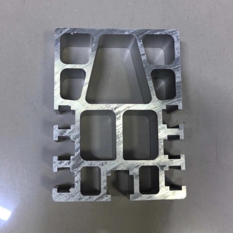
Semiconductor OHT Rail Aluminum Profile
OHT rails for wafer fabs, 3.5 m/s straight and 0.7 m/s in curves, R500 mm, +/-3 mm repeatability, 40 kg FOUP load. Section per drawing.
Product Details
Short answer: a semiconductor OHT rail is the overhead track that an overhead hoist vehicle runs on inside a wafer fab, carrying FOUPs above the process equipment instead of through the cleanroom floor. Working reference: straight-section speed up to 3.5 m/s, curve speed up to 0.7 m/s, minimum radius R500 mm, positioning repeatability within ±3 mm, load up to about 40 kg for a 12-inch FOUP. What the rail is really judged on is particle generation and running smoothness. Section and tolerance are set by your drawing.
What it is used for
It carries the AMHS overhead transport system in 12-inch and panel fabs: OHT vehicles moving FOUPs between process tools, stockers and metrology stations. A large fab moves well over 100,000 FOUP transfers a day on a single network, which means the rail is in continuous use rather than occasional use.
Running overhead is what makes the layout possible. The system occupies the space above the equipment, so it does not consume cleanroom floor area, which is the most expensive floor space in the building. A typical installation fits into a building height of about 2.7 m, which is why the rail section is compact rather than deep.
Everything about the part follows from the environment: the rail has to run for years inside a cleanroom without shedding particles, without generating wear debris at the wheel contact, and without introducing vibration into a vehicle that is carrying 25 wafers at a time.
Specifications
| Item | Working reference | How it is set |
|---|---|---|
| Alloy | 6063-T5 or 6061-T6 | Chosen against your load and span |
| Straight-section speed | Up to 3.5 m/s | Set by the vehicle and the system |
| Curve speed | Up to 0.7 m/s | Set by the payload, not the rail |
| Minimum radius | R500 mm for 45 and 90 degree turns | Set by your layout |
| Positioning repeatability | Within ±3 mm at a stop | System requirement, per your drawing |
| Load | Up to about 40 kg, 12-inch FOUP | Set by your vehicle |
| Surface | Anodized on all exposed faces, including the running face | Set by the cleanliness requirement |
| Cleanliness | Class 100–1000 compatible after installation wipe-down | Set by your acceptance method |
How it is made
- The section is extruded in one piece, with the running geometry formed in the die so there is no joint along the track path.
- Lengths are cut and the joint faces machined so the transition is step-free; a step at a joint is a vibration source and a wear source at the same time.
- Holes and hanger positions are machined on a single datum, because the rail's alignment relative to the tool ports is what the system depends on.
- Anodizing covers the exposed surfaces, including the running face, so the wheel contacts an oxide surface rather than bare aluminum.
- The parts are cleaned and packed for cleanroom entry, and splicing is done in a clean booth or a local Class 100 environment.
Where this fits
It fits when the fab uses overhead transport, when the ceiling height is limited, and when the rail has to run continuously without becoming a particle source.
Where it does not fit: if the transport is floor-based AGV or a conveyor, this is the wrong system. If the building has no ceiling structure able to carry a hanger network, the overhead approach needs to be evaluated before the rail is. And if the requirement is a short, low-duty link, a simple track may be sufficient and a full AMHS rail is over-specified.
What actually decides performance here
Particles, not speed, are the primary metric. A cleanroom at Class 100 to 1000 counts particles in the air, and a rail that wears against a wheel produces exactly the particles that count is measuring. Bare aluminum running against a wheel generates aluminum debris, which is both a particle and a metallic contaminant. Anodizing changes the contact from aluminum-on-wheel to oxide-on-wheel, which is harder, smoother and far less prone to smearing. That is why the running face is anodized here, which is the opposite of the rule for a conductor rail, where the oxide would be an insulator and must be masked off. Same process, opposite decision, because the function is different.
And the coating itself must not shed. An anodized layer that is porous, poorly sealed or applied over a badly pre-treated surface can flake, and flaking oxide is a particle source in its own right. The requirement is a coherent, sealed film with no exposed bare aluminum at the wear track, plus handling discipline so a scratched rail does not enter the cleanroom. This is a process-control question, and it is why the finish specification on an OHT rail is longer than on an industrial track.
A step at a joint is felt as vibration. The vehicle runs at up to 3.5 m/s on the straight. At that speed, a step of a fraction of a millimeter at a joint is an impact that travels into the hoist and into the FOUP. The result is vibration at the wafer, and the wafer is the part that cannot be replaced. Joint faces are machined, not cut, for this reason.
±3 mm is a system number, and the rail only supplies repetition. The vehicle finds its stop with its own sensors and the control system. What the rail has to provide is that the same physical position is reached the same way each time, so the vehicle's correction is the same each time. If the rail is installed with a systematic offset, every stop on that section is off in the same direction, and software cannot correct a bias it did not cause. Installation datum and rail-to-rail alignment therefore matter as much as the machining tolerance, and they cannot be inspected into a part after the fact.
The 0.7 m/s curve limit is about the wafers, not the vehicle. A FOUP holds 25 wafers stacked in slots with clearance. Lateral acceleration in a turn pushes them against the slot walls; too much and they shift, rub or chip, and any of those produces particles or scrap. The vehicle could take the turn faster. The payload cannot. That is why the curve speed is a fixed system limit rather than something to be negotiated, and why the minimum radius of R500 mm is about fitting the network into a dense ceiling rather than about going quickly.
What to send for a quote
- The AMHS layout with straight runs, turns and the tool port positions
- Vehicle model and the FOUP or carrier type, since the interface decides the section
- Ceiling height and the hanger arrangement available
- The positioning requirement at the tool ports
- Cleanroom class and the acceptance method for particles
FAQ
What speed, radius and tolerance can you hold?
The rail supports straight speeds up to 3.5 m/s, curve speeds up to 0.7 m/s, a minimum radius of R500 mm, and positioning repeatability within ±3 mm at the stop as a system figure. The section and machining tolerance are set by your drawing, and we state the achievable running-face and joint condition rather than a generic accuracy claim.
Why does the curve speed limit sit at 0.7 m/s?
Because of the payload. A FOUP carries 25 wafers with clearance in their slots, and lateral acceleration in a turn makes them move. Above a modest lateral load they rub or chip, which creates particles and scrap. The vehicle is capable of more; the wafers are not, so the limit is set at the wafer.
Why is the rail anodized if the oxide is a hard, brittle layer?
Because the alternative is bare aluminum wearing against a wheel in a cleanroom. The oxide is harder and smoother and produces far less debris than bare metal. The requirement is a properly sealed film, because a flaking coating is itself a particle source. On a conductor rail the same oxide would be an insulator and is masked off, which shows the decision is driven by function.
What positioning accuracy does the rail contribute?
Repeatability, not absolute position. The vehicle's sensors and control give the accuracy at the stop, and the rail has to make every approach to that position identical. A systematic installation offset shifts every stop on a section, and no control system can correct a bias it did not create.
How are the joints handled in a cleanroom?
The joint faces are machined step-free, and splicing is done in a clean booth or a local Class 100 environment. After installation the rail is wiped with a lint-free cloth and isopropyl alcohol so that handling residue does not show up in the particle count.
Is it compatible with the main OHT vehicle brands?
In most cases yes, if the running geometry and the hanger interface match. We need the vehicle's rail interface specification or an existing rail sample, because a small difference in the running face or the hanger position turns into vibration, wear or a docking error rather than an obvious mismatch.
Next step
Send the AMHS layout and the vehicle interface specification. We will come back with a section, a joint plan and a statement of the running-face and alignment condition we can hold against your drawing.
Email: linjunbing@truetrustlv.com | Call or WhatsApp: +86 136 6644 0600
GET A QUOTE
Once you have submitted your requirements, we will contact you as soon as possible regarding your product inquiry.:Semiconductor OHT Rail Aluminum Profile