
Automated logistics
KBK I-Beam Aluminum Rail
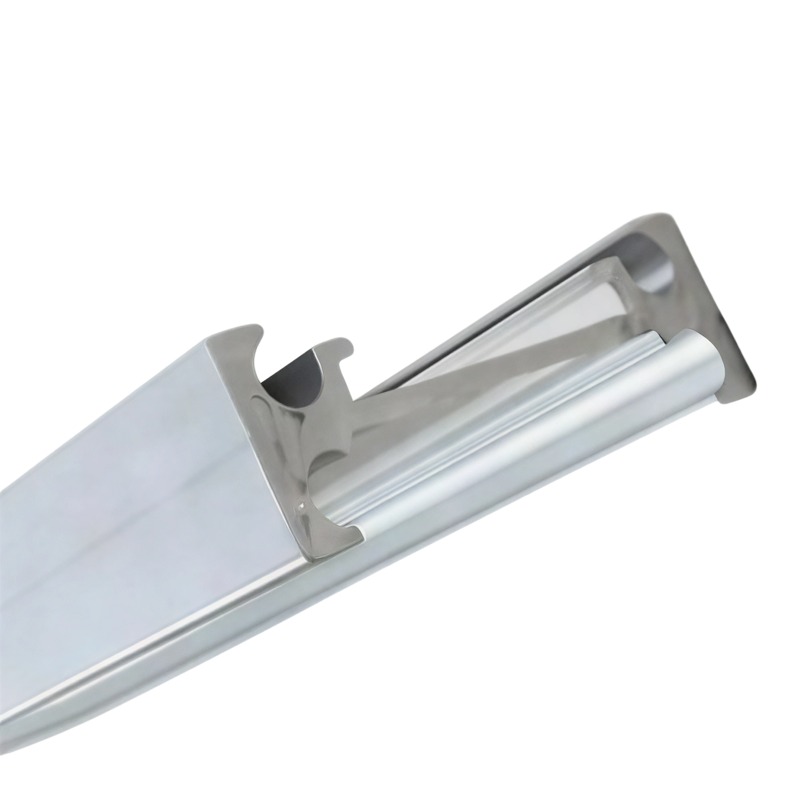
KBK I-beam rails in 6063-T5 from 2.7 kg/m, 125-2000 kg load, curve radius from 1.5 m, conductor bar optional. Section and load per drawing.
Product Details
Short answer: a KBK I-beam rail is an extruded aluminum track with an I-shaped section that carries a light crane or a suspension trolley. The load range runs about 125 kg to 2000 kg, and the rail weighs as little as 2.7 kg per meter, roughly a third of the steel rail it replaces. It takes straight runs, curves down to a 1.5 m radius, and switches, and it can carry a conductor bar inside the section. Section size and alloy are set by your load case and your layout.
What it is used for
It makes up the rail network of a KBK light crane system, and it also serves as the running track for suspension trolleys, hoists, balancers, manipulator arms and workstation crane structures in assembly shops, machining cells, warehouses and maintenance bays.
The usual layout mixes all three elements: a straight run along the bay, a curve that takes the track around a corner or between two aisles, and a switch where two lines meet. The profile is designed to accept all of them from one section family, so the system is built from a small number of parts rather than from a custom fabrication for every corner.
Specifications
| Item | Working reference | How it is set |
|---|---|---|
| Alloy | 6063-T5, or 6061-T6 for higher load | Chosen against your load case |
| Load range | 125–2000 kg per rail span | Set by your drawing and the support spacing |
| Rail weight | From 2.7 kg per meter | Result of the section, fixed by the profile |
| Curve radius | Down to 1.5 m, smaller on request | Set by your layout |
| Section | I-beam, with a lower flange that carries the trolley wheels | Set by your drawing |
| Conductor bar | Can be integrated into the section | Set by your power supply design |
| Surface | Anodized, with hard anodizing on the running flange where wear matters | Set by your duty cycle |
| Machining | Cut, drilled, tapped, end-machined | Per your drawing |
How it is made
- The I-section is extruded in one piece, so the flanges and the web are continuous metal rather than a welded fabrication.
- Lengths are cut and the ends machined square for jointing or for an end stop.
- Curved lengths are roll bent, with the radius checked against a template before any holes are drilled.
- Holes, splice plates and hanger positions are machined after bending, because bending shifts hole positions along the length.
- Anodizing follows, with the running flange treated according to the duty the customer specifies.
Where this fits
It fits when the building structure has a limited spare load, when the layout needs curves and switches in a tight bay, and when the crane or trolley duty is light to medium with a defined load.
Where it does not fit: above a certain span and load, steel is the correct material and aluminum becomes a weight saving that costs stiffness. If the rail has to resist a high duty cycle with heavy wheel loads, the running surface will wear and a steel track or a hardened insert is the better answer. And if the bay layout is a single straight run with no curve, a standard section from any supplier will do the job.
The three things that decide whether this works
The I-section carries load in its flanges, not its height. The trolley wheels run on the underside of the lower flange, so the load enters the profile there and travels out to the web. What carries it is the flange thickness and the root radius where the flange meets the web, not the overall section height on a catalogue page. Two rails of the same height can have very different capacities for this reason, and choosing by height is how a system ends up under-rated.
Aluminum is soft where the wheels run. A steel rail tolerates a hard wheel rolling on it for years. Aluminum does not, and the failure mode is a groove worn into the lower flange that the trolley then follows. That groove is not only a wear item, it changes the rolling resistance and can make the trolley track badly. The mitigations are practical and cheap if designed in: hard anodizing on the running flange, a wider wheel to spread the contact stress, a larger wheel diameter, or a polymer wheel where the load allows.
The weight saving is worth more than the price difference. Comparing a KBK aluminum rail with a steel rail on price per meter gets the answer wrong. The steel rail weighs roughly three times as much, and that weight has to be carried by the building structure: more hangers, shorter hanger spacing, sometimes reinforcement of the roof steel. Add the installation time for a heavier system and the aluminum rail frequently wins on total installed cost even when its unit price is higher. The comparison that matters is system cost, and it is worth asking for it that way.
What to send for a quote
- The KBK layout drawing, with the straight runs, curves, switches and hanger positions
- Load per trolley and the number of trolleys on one rail at once
- Span between hangers, because it sets the section size
- Duty cycle and whether the trolley wheels are steel, nylon or polyurethane
- Whether a conductor bar has to run inside the section
FAQ
What load and tolerance can you hold?
The rail family covers roughly 125 kg to 2000 kg per span, with section dimensions held to the tolerance on your drawing and the running flange flatness controlled because the trolley feels it. The value on your order is set by your drawing; the load figure we quote is for the section and hanger spacing you specify, not a generic maximum.
Why aluminum instead of steel for a KBK rail?
Weight. At about 2.7 kg per meter against roughly three times that for steel, the aluminum rail reduces the load on the building structure, allows wider hanger spacing and makes installation faster. On a system with a tight roof structure that is often worth more than the difference in unit price.
How do I choose between 125 kg and 2000 kg?
From the actual load, the number of trolleys sharing the rail, and the hanger spacing, not from the headline range. A rail rated at 2000 kg over a short span behaves differently over a long one, and two trolleys close together load the section differently from one trolley. Send the layout and we will size it.
What curve radius can you make?
Down to 1.5 m as standard, with smaller radii on request. The limit is the section: bending an I-beam tighter than the flange can take causes the flange to buckle or the web to wrinkle. Where a layout needs a very tight corner, the answer is often a fabricated corner piece rather than a bent rail.
Can the power supply run inside the rail?
Yes, the section can accept a conductor bar, which keeps the cable run out of the way and reduces the chance of damage in a busy bay. The conductor bar itself is a separate specification and is quoted as such.
Will it fit an existing KBK system from another supplier?
Often, if the connection geometry and the trolley wheel profile match. We need the existing rail's section drawing or a sample to confirm, because the flange thickness and the wheel contact geometry are what decide whether a trolley runs correctly on a new rail.
Next step
Send the layout with the loads, the hanger spacing and the trolley details. We will come back with a section recommendation, a curve and switch plan, and a written statement of what we can hold against your drawing.
Email: linjunbing@truetrustlv.com | Call or WhatsApp: +86 136 6644 0600
GET A QUOTE
Once you have submitted your requirements, we will contact you as soon as possible regarding your product inquiry.:KBK I-Beam Aluminum Rail