
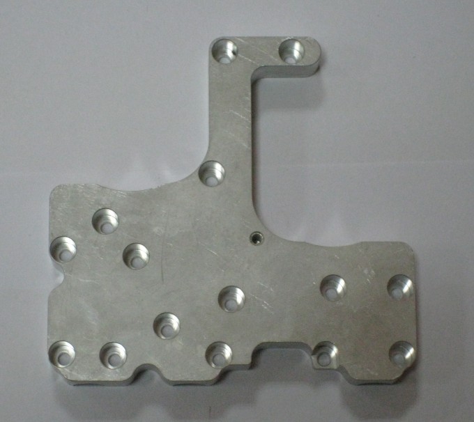
Aluminum Product Processing
Aluminum Profile CNC Turn-Mill Machining - One-Setup Accuracy
Turn-mill is bought for concentricity, not speed. What one setup removes from the stack, chuck distortion, centrifugal jaw force, and C-axis scaling.
Product Details
Turn-mill is usually sold on speed: fewer setups, less handling, 30 to 50 per cent faster. That is true, and it is not the reason to use it. The reason is that a single setup removes a specific error from the part — the error that comes from taking a part out of a chuck and putting it back in, and expecting the second fixture to agree with the first.
A three-jaw chuck re-clamped on the same diameter repeats to about 0.02–0.05 mm, and that error lands directly between the turned features and the milled features. On a part where a bore has to be concentric with an outside diameter that also carries a milled keyway and a ring of tapped holes, that is the error that decides whether the assembly runs true.
We turn and mill aluminium parts on turn-mill centres and five-axis equipment, up to 6,500 mm in length and 400 mm swing, to a reference of ±0.01 mm on turned features, ±0.02 mm on milled and drilled features, and Ra ≤ 0.8 µm.
The value of turn-mill is concentricity, not speed
Consider a flanged sleeve: outside diameter, a through bore, a face, four drilled holes on a pitch circle, and a keyway in the bore. Done the conventional way, the sequence is turn the outside and the bore, remove, then mill the keyway and drill the holes with the part located on its outside diameter. Every milled feature is now positioned relative to a diameter that was itself gripped by a chuck a second time.
Done on a turn-mill centre, the part is gripped once. The outside diameter, the bore and the face are turned from one spindle rotation; the part is then indexed on the C-axis and the keyway, holes and slots are machined without releasing it. Everything shares one axis, and the relationship between the features is set by the machine's geometry rather than by a fixture's repeatability.
| Error source | Two setups (lathe then mill) | One setup (turn-mill) |
|---|---|---|
| Concentricity of bore to outside diameter | Chuck re-clamp adds 0.02–0.05 mm | Set by spindle rotation, typically ≤ 0.01 mm |
| Face squareness to the axis | Second clamping on a turned face adds a tilt | Turned in the same rotation as the diameter |
| Hole pattern to the bore | Fixture location plus re-clamp error | C-axis indexing from the same datum |
| Handling and re-fixturing time | Two setups, two waits, two first-piece checks | One setup, one first-piece check |
| Scrap risk | Error found after the part is already half machined | Error found before the part leaves the machine |
The time saving is real but it is a by-product. If a part has no rotational features there is nothing to gain, and a turn-mill centre is the wrong machine.
C-axis indexing: accurate at the centre, magnified at the rim
On a turn-mill centre, the angular position of a milled feature is set by the C-axis. That accuracy is quoted in degrees, which hides the fact that its effect on the part scales with radius. A C-axis accurate to ±0.01° puts a feature at the 100 mm radius about ±0.017 mm from nominal, and at the 200 mm radius about ±0.035 mm.
So on a large flange, the holes near the bore hold position easily and the holes near the rim are the ones that drift. Two practical consequences: a drawing that calls the same position tolerance on all holes of a large pitch circle is calling a tolerance the machine can only hold on the inner ones, and the fix is to define the pattern by angular position and pitch circle diameter rather than by X-Y coordinates, which is how it will actually be inspected.
The chuck deforms a thin sleeve before the tool touches it
A thin-walled sleeve held in a three-jaw chuck is squeezed into a triangle at three points. The bore is then turned round in a part that is not round, and when the chuck is released the bore becomes triangular by 0.05 to 0.2 mm depending on wall thickness and jaw pressure. The measurement in the chuck is perfect; the measurement after release is not.
| Holding method | Repeatability | Effect on a thin wall | When it is the right choice |
|---|---|---|---|
| Three-jaw scroll chuck | 0.02–0.05 mm | Three-point distortion; worst case for a thin sleeve | Solid parts, roughing |
| Soft bored jaws, part profile | 0.01–0.02 mm | Load spread over a larger arc; much reduced | General finishing |
| Six-point or collet | 0.005–0.015 mm | Uniform radial load, minimal distortion | Thin-walled rounds within collet range |
| Expanding mandrel on the bore | 0.005–0.01 mm | Loads outward, so the outside diameter is cut true | Second operation on a finished bore |
| Fusible alloy or wax fill | Depends on the fill | Supports the wall from inside completely | Very thin walls, low quantity |
The rule is the same as on a milling machine: the finishing cut is taken with the least holding force that still drives the part, and every heavy operation happens before it.
Centrifugal force: the error that only exists on a lathe
On a lathe, the jaws are rotating with the part, and so is their mass. At speed, each jaw pulls outward with a force proportional to its mass, its centre of mass radius, and the square of the angular velocity. The arithmetic is unforgiving because of the square:
A jaw assembly of about 1 kg with its centre of mass at 50 mm radius, running at 3,000 rpm (314 rad/s), generates roughly 4.9 kN of outward force. That force partly cancels the clamping force the chuck applied statically. Spin the same chuck at 6,000 rpm and it is four times larger, around 19.6 kN — enough to release a thin part entirely.
Two consequences that matter to a customer:
- Thin-walled parts must be turned at limited speed, not because the tool cannot cut faster but because the chuck cannot hold faster. This is why a wall thickness under 2 mm can put a ceiling on the cutting parameters, and why the quoted cycle time for a thin sleeve is longer than for a solid bar of the same size.
- The achievable roundness of a thin sleeve depends on the speed it was cut at. A part turned at 1,500 rpm and a part turned at 4,000 rpm are not the same part, even with identical tools and feeds.
Where the sub-spindle hand-off costs you accuracy
On a long part, or one that has to be machined from both ends, the second operation is often done by transferring the part from the main spindle to the sub-spindle inside the machine. That eliminates the operator and the queue, but it does not eliminate the error — it relocates it. The two spindles have to be aligned to each other, and their alignment is a machine condition that drifts with temperature and with any bump.
So a part machined from both ends on a turn-mill centre holds concentricity between the two ends to the machine's spindle alignment, typically a few hundredths of a millimetre, rather than to a re-clamp error of 0.02–0.05 mm. It is better — but it is not the same as a single-setup part, and a drawing that assumes a single setup for a part that physically needs two operations will not be met by either method.
The power turret is not a machining centre
Milling on a turn-mill centre is done with a driven tool held in a turret. That tool is smaller and less rigidly supported than the same tool in a machining centre spindle, and the workpiece is a rotating cylinder rather than a block on a table. The consequences are practical:
- Light milling only. Slots, keyways, flats and small pockets are fine. Deep pocketing and heavy face milling belong on a machining centre.
- Tool overhang matters more, because the driven tool has to reach past the turret body to the part.
- Surface finish on a milled face comes from the interpolation of a rotating part against a small cutter, so it is usually a step behind what a machining centre produces on the same feature.
Turn-mill or five-axis milling: how we choose
The dividing line is the part's dominant geometry, not its complexity:
| Part characteristic | Turn-mill centre | Five-axis machining centre |
|---|---|---|
| Dominant geometry | Rotational: shafts, sleeves, flanges, valve bodies | Prismatic: housings, brackets, plates, cavities |
| Best at | Concentric features, faces, pitch circles, keyways | Deep pockets, complex contours, five-face access |
| Milling capability | Light to medium, driven tools in a turret | Heavy, large cutters, high metal removal |
| Typical part size | Up to Ø400 mm swing, 6,500 mm long | Up to 6,500 × 550 × 500 mm envelope |
| Concentricity | Held by the spindle, best in class | Requires a fixture and a datum, second best |
Many parts want both, and then the question is which machine does the second operation — a small number of parts that need both in one setup are worth quoting deliberately rather than routing through the standard process.
Slender parts and the steady rest
A shaft with a length-to-diameter ratio above about 8 deflects away from the tool under radial cutting force, and the part comes out tapered: correct at the chuck, small at the free end. Above 10, a steady rest or a tailstock is not optional.
With a steady rest the part is supported at an intermediate point, but the support itself becomes a source of error: the pads have to be adjusted to the finished diameter, they wear, and they can mark the surface. For a long slender part with a tight diameter tolerance, the sequence is usually rough between centres, allow the part to settle, then finish with the rest freshly adjusted.
There is also a thermal element on long parts. A lathe that has been running for half an hour has a spindle that is warmer than it was at the first cut, and the headstock grows axially. On a 6 m part this can move the free end by 0.01 to 0.03 mm over a run. Long parts are measured against a stated temperature, or probed, rather than assumed.
Specifications
| Item | Reference value |
|---|---|
| Equipment | Turn-mill centres with driven tools and C-axis; five-axis machining centres |
| Turning accuracy | ±0.01 mm |
| Milling and drilling position accuracy | ±0.02 mm |
| Combined dimensional accuracy | ±0.02 mm |
| Surface roughness | Ra ≤ 0.8 µm; Ra ≤ 0.4 µm on request |
| Maximum part length | 6,500 mm |
| Maximum swing diameter | Ø400 mm |
| Operations in one setup | Turn, bore, face, mill, keyway, drill, tap, chamfer |
| C-axis indexing | Angular; effect on position scales with radius |
| Thread class | 6H |
| Alloys | 6061-T6, 6063-T5, 6005-T6, 6082-T6, 7075-T5 |
| Batch size | Quoted per drawing; prototype quantities accepted |
| Standard | GB/T 6892-2023 high precision grade |
Where it does not fit
- Parts with no rotational features. A bracket or a housing gains nothing from a lathe spindle and loses the rigidity of a machining centre.
- Heavy milling on a rotational part. A flange that needs a deep pocket as well as a turned bore is usually better split: turn on the lathe, then mill on a machining centre, accepting the second setup.
- Very thin sleeves at high speed. The chuck, not the tool, sets the limit. Below about 1.5 mm wall the achievable roundness and the achievable speed both fall away.
- Parts beyond Ø400 mm swing. Large flanges go on a vertical lathe or a boring mill, and the concentricity story changes accordingly.
- One or two pieces of a simple turned part. A conventional lathe is cheaper per part at that quantity; the setup advantage of turn-mill needs a batch to pay for itself.
FAQ
What accuracy can you hold on a turn-mill part?
Reference ±0.01 mm on turned diameters, ±0.02 mm on milled and drilled features, with concentricity between features held by the spindle rather than by a fixture, and Ra ≤ 0.8 µm, or Ra ≤ 0.4 µm on request. Those are capability references: the value on your order is set by your drawing, and a thin wall or a long slender part will limit what is achievable. We confirm the achievable values in writing before quoting.
Does one setup really remove the re-clamping error?
Yes, for features machined in that setup. It does not help a part that physically needs two operations — for example one that must be machined from both ends beyond the machine's reach. In that case the error moves to the sub-spindle hand-off rather than disappearing.
Why does my sleeve come out oval after turning?
Because it was round in the chuck and released afterwards. A three-jaw chuck distorts a thin wall at three points; the bore is cut round in a distorted part and springs to a triangle or an oval when the jaws open. Softer jaws, a collet, or an expanding mandrel on the bore solve it, and so does finishing with a light clamping force.
Can turn-mill replace a machining centre for a housing?
Only where the housing is dominated by rotational features. For a box-shaped housing with deep pockets, a five-axis machining centre is faster and more accurate, because the driven tool in a turret cannot take the same depth of cut or reach as far as a spindle.
What surface finish can be achieved on a turned diameter?
Ra 0.8 µm as standard and Ra 0.4 µm on request. In aluminium the limit is usually not the tool but the vibration of a thin wall and the marking left by the chuck or the steady rest, so the finish has to be considered together with how the part is held.
Can you hold a tight tolerance on a long shaft?
Up to a point, and the point is deflection. Beyond a length-to-diameter ratio of about 8, the part is pushed away by the cutting force and comes out tapered; a steady rest or tailstock is needed, and the finishing pass has to be taken with the support freshly adjusted. We will say in the quotation where we expect the limit to be.
Is there a minimum quantity for turn-mill work?
No fixed minimum. The economics are different from single-process machining, because the setup is more expensive and the per-piece time is lower, so the process pays off from a batch of roughly twenty parts upward. Below that it is quoted case by case.
Send your drawing
Email the part drawing with the concentricity and runout callouts, the datum for the milled features and the wall thicknesses to linjunbing@truetrustlv.com, or send it on WhatsApp at +86 136 6644 0600. You will get a proposed operation sequence, a note on which features force a second setup, and a written statement of the achievable concentricity and tolerance.
GET A QUOTE
Once you have submitted your requirements, we will contact you as soon as possible regarding your product inquiry.:Aluminum Profile CNC Turn-Mill Machining - One-Setup Accuracy