
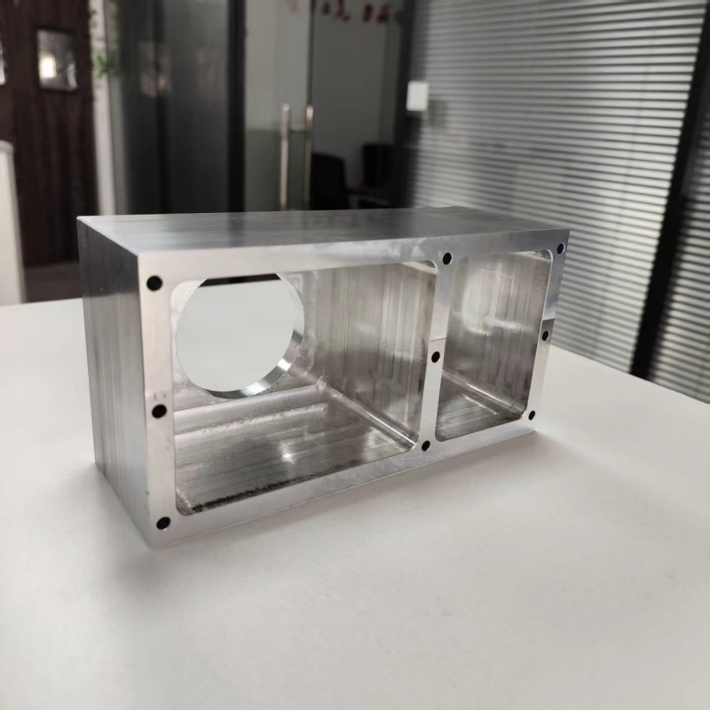
Aluminum Product Processing
Aluminum Profile CNC Milling - Holding Tolerance Under Load
Why most milling error comes from cutting force, not machine accuracy: tool deflection, clamp release, thermal drift over 6.5 m, and the spring pass.
Product Details
On a machined aluminium profile, most of the dimensional error does not come from the machine's positioning accuracy. It comes from the force the cutter applies and the way the part moves under that force. A centre that repeats to ±0.005 mm will still produce a wall that measures 0.15 mm thin in the middle, because the wall deflects while the tooth is passing and springs back after it has gone.
We mill custom aluminium profiles and parts on three-axis and five-axis vertical centres and a gantry mill, up to 6,500 × 550 × 500 mm, to a reference of ±0.02 mm and Ra ≤ 1.6 µm, in 6061-T6, 6063-T5, 6005-T6, 6082-T6 and 7075-T5.
What follows is how the tolerance on a milled part is actually made, and where it is lost.
Why a milling tolerance is a force problem, not a machine problem
A cutter is a cantilever. Deflection at the tip follows the standard beam relation: deflection is proportional to cutting force times overhang cubed, divided by three times the modulus and the second moment of area of the tool section. Put numbers into it for a typical finishing cut:
- Ø12 mm solid carbide end mill, 40 mm overhang, radial depth 0.5 mm in 6061.
- Cutting force in the region of 300 N at that engagement.
- Tool deflection at the tip: approximately 0.09 mm.
That is four and a half times the positioning accuracy of the machine, and nine times a ±0.01 mm drawing callout. On aluminium it is worse than the same cut in steel, because aluminium's modulus is about 69–71 GPa against roughly 200 GPa for steel: for the same force, three times the deflection.
So the tolerance is not achieved by buying a better machine. It is achieved by keeping the force small at the moment the final surface is generated, and by making sure the part cannot move when the force arrives.
| Source of error | Typical magnitude | Where it shows up | How it is controlled |
|---|---|---|---|
| Axis positioning | 0.005–0.02 mm | Uniformly across every feature | Machine specification; rarely the limiting factor |
| Tool deflection under load | 0.02–0.10 mm | Middle of a long wall, deepest point of a pocket | Light finishing cut, shorter overhang, relieved tooling |
| Clamping deflection | 0.02–0.20 mm | After unclamping: oval bores, bowed flanges | Lower clamping force, more support points, finish after release |
| Thermal drift along a long part | 0.05–0.77 mm | One end of the profile relative to the other | Controlled shop temperature, probing and compensation |
| Residual stress release | 0.05–0.30 mm | Bowing after metal is removed from one side | Stress-relieved stock, symmetric removal, rough and finish separately |
Two of these five are the machine. Three are the process. The process ones are the ones that produce the phone call after the parts arrive.
Climb or conventional: it decides which way the wall moves
In climb milling the tooth enters the cut at full chip thickness and the feed direction matches the cutter rotation at the point of contact. The resultant force pulls the workpiece towards the cutter. In conventional milling the tooth enters at zero thickness, rubs before it cuts, and the force pushes the workpiece away.
On a solid block this is a surface-finish question. On a thin wall it is a dimensional question, because the wall moves in the direction the force points:
| Item | Climb milling | Conventional milling |
|---|---|---|
| Chip formation | Thick to thin; tooth starts loaded | Thin to thick; tooth rubs at entry |
| Force on a thin wall | Pulls the wall towards the cutter, so the wall thins | Pushes the wall away, so the wall stays thick |
| Surface finish | Better; less rubbing and less work hardening | Poorer; entry rubbing marks |
| Tool life in aluminium | Longer at the same parameters | Shorter, built-up edge more likely |
| Fixture requirement | Backing support behind the wall | Rigid push-off resistance, or the part lifts |
| Our default | Climb for finishing | Only where the setup cannot back up the wall |
We climb mill aluminium as standard. Where a wall is thin enough that climb milling would pull it out of tolerance, the answer is not to switch direction — it is to back the wall up with a support, reduce the radial engagement, or leave the wall to a separate light pass after the rest of the part is finished.
Clamping deflects the part, and it springs back afterwards
This is the error that survives measurement at the machine. A hollow section with 1.5 mm walls, held in a vice across 40 mm of width, is squeezed into an oval by the jaws. The cutter then produces a perfectly round bore in a part that is not round. Release the vice and the bore becomes oval by whatever the jaws deflected — typically 0.1 to 0.3 mm on a thin hollow section.
The controls, in the order we apply them:
- Jaws machined to the part profile. Soft jaws bored or milled to match the section spread the load over the whole face instead of two line contacts.
- Torque-controlled clamping. A torque wrench on the vice, or a low-pressure hydraulic clamp, so the force is the same on every part and is the minimum that holds it.
- Internal support. Fusible alloy, wax, or an expanding mandrel inside a hollow section, removed after machining.
- Finish after release. Rough with heavy clamping, release, re-clamp lightly, then take the finishing cut. The finishing cut is then taken in the part's relaxed state.
- Vacuum or adhesive fixturing for flat plate and thin panels, where clamping force is replaced by distributed holding.
The rule we work to
The finishing cut should be taken with the least clamping force that still holds the part, in the part's own relaxed shape. Every operation that removes a lot of metal should happen before that cut, not after it.
Long profiles: straightness has to be machined in, not assumed
A 6,500 mm extrusion is a flexible beam before it is a precision part. Two effects matter:
Self-weight sag. Supported at two points only, a 6.5 m section sags at mid-span by a millimetre or more depending on its stiffness, and the sag changes as metal is removed. We support at 1.2 to 1.5 m intervals and indicate the top face before cutting.
Thermal expansion. Aluminium expands at 23.6 µm per metre per kelvin. Over 6,500 mm, a 5 °C change in shop temperature moves one end 0.77 mm relative to the other. That is larger than the tolerance on most drawings, so a long part is either machined in a temperature-controlled area, or probed on the machine and compensated, or both.
The practical consequence for a designer: features at opposite ends of a long profile should be machined in one setup wherever the machine envelope allows it. Re-datuming a 6.5 m part between operations adds the full length of the part to the tolerance stack.
What each milling operation is actually for
The same machine performs all of these, but they load the part differently, so they fail differently.
| Operation | Force direction | Characteristic error | Best used for |
|---|---|---|---|
| Face milling | Axial, into a supported face | Flatness and cupping; a face mill can dish a thin panel | Datum faces, mounting planes, heat-sink bases |
| Peripheral (contour) milling | Radial, sideways | Wall deflection and taper on deep contours | Outlines, connector bodies, flange profiles |
| Slot milling | Both flanks loaded at full width | Slot narrows at depth, slot bows along its length | T-slots, V-slots, U-slots, guide mounting grooves |
| Pocket and cavity milling | Combined, with chip evacuation problems | Corner radius limit and floor flatness | Housings, RF cavities, sensor bodies |
| Circular interpolation | Radial, unbalanced on one side | Out-of-round bore from tool deflection | Bores a boring bar cannot reach, large diameters |
| Helical or ramp entry | Progressive, no centre cutting | Entry marks if the ramp angle is too steep | Entering any closed pocket without plunging |
The one worth flagging to a designer is slot milling. A cutter taking a full-width slot is loaded on both flanks with no relief, and the chips have only one way out — backwards along the slot. A slot 12 mm wide and 60 mm long is machined faster and more accurately with a 6 mm cutter in two passes than with a 12 mm cutter in one, even though it looks like more work on the route card.
The finishing pass is where the tolerance is made
Because the deflection happens while cutting, a single finishing pass leaves the deflected surface behind. The correction is a spring pass: repeat the same tool path with no additional radial depth of cut, so the cutter removes only the material that was pushed out of the way the first time. On a wall in the 1.5–3 mm range it typically removes 0.02 to 0.05 mm, which is exactly the error that was there.
The sequence we use when a tolerance is tight:
- Rough, leaving 0.3–0.4 mm on all machined faces.
- Release clamping stress, allow the part to settle, re-clamp lightly.
- Semi-finish, leaving 0.10–0.15 mm.
- Measure on the machine where the feature matters.
- Finish, then spring pass on the critical walls.
On a part where two operations are needed and the tolerance is under ±0.03 mm, in-process probing closes the loop: the machine measures the semi-finished feature and offsets the finishing path to suit, rather than trusting the nominal.
Specifications
| Item | Reference value |
|---|---|
| Maximum envelope | 6,500 × 550 × 500 mm |
| Machine types | Three-axis and five-axis vertical centres, gantry mill |
| Positioning accuracy | ±0.02 mm |
| Repeat positioning accuracy | ±0.005 mm |
| Flatness on a faced surface | ±0.02 mm reference |
| Contour and slot accuracy | ±0.02 mm reference |
| Surface roughness | Ra ≤ 1.6 µm standard; Ra ≤ 0.8 µm on request |
| Spindle speed | Up to 24,000 rpm |
| Alloys | 6061-T6, 6063-T5, 6005-T6, 6082-T6, 7075-T5 |
| Thermal expansion | 23.6 µm/m/K; 767 µm over 6.5 m for a 5 °C swing |
| Coolant and chip control | Through-spindle high pressure, flood, or air blast |
| Batch size | Quoted per drawing; prototype quantities accepted |
| Standard | GB/T 6892-2023 high precision grade |
Where it does not fit
Milling is the right process for most features on an aluminium profile, but not for all of them, and saying so saves a redesign.
- Deep, narrow cavities with small corner radii. Below about depth/10 in corner radius the cutter cannot reach without a relieved tool or five-axis access, and the cost climbs accordingly. A cavity page covers this in detail.
- Walls under 0.8 mm. Machinable in short lengths, but the wall deflects away from the cutter, the finish becomes inconsistent, and holding ±0.05 mm on the wall thickness is not realistic.
- Bores with a length-to-diameter ratio above about 4. Interpolation leaves the bore tapered and out of round. That is boring-bar territory, or a reamed hole, not milling.
- Features that need to be sharper than the cutter. An internal corner is a radius, always. If the drawing shows a sharp internal corner, the part as drawn cannot be milled.
- Very high volumes of a simple part. Above a certain annual quantity, a die casting or an extrusion with the feature built into the die is cheaper than machining every piece.
FAQ
What tolerance can you hold on a milled profile?
Reference ±0.02 mm on position, flatness, contour and slot width, with repeat positioning at ±0.005 mm and Ra ≤ 1.6 µm. Those are capability references: the value on your order is set by your drawing, and the achievable figure depends on wall stiffness, feature depth and how much metal is removed. We state the achievable tolerance for your part in writing with the quotation, before you commit.
Why does the middle of a long machined face come out low?
Either tool deflection at mid-span or the part sagging between supports. Both produce a low middle, and both are corrected the same way: more support points, a lighter finishing cut, and a spring pass with no additional depth so the deflected material is removed.
Can you mill a profile that is already anodised?
You can, but the cut face will be bare aluminium and the anodic layer at the cut edge will chip and flake. Machining before anodising is the correct sequence. If a part must be machined after coating for a functional reason, plan for a touch-up and expect a visible edge.
How is five-axis different in practice?
It is not mainly about complex surfaces. Five-axis matters because it lets the tool reach a feature at a shorter effective overhang, and because it allows several faces to be machined without re-clamping. Both of those attack the two largest error sources on this page: tool deflection and clamping deflection.
What surface finish should I specify?
Specify Ra only where it functions. Ra 1.6 µm is our standard for a machined face and is right for most sealing and mounting surfaces. Ra 0.8 µm is available but costs a finishing pass and is usually only needed on a sliding or sealing face. Cosmetic faces are better specified by appearance and then anodised or bead blasted, which hides tool marks far more effectively than a tighter Ra.
Do you machine from our extrusion or from stock?
Either. If the profile already exists in our die library or yours, we machine it. If it does not, the die has to be developed first, and that is a separate lead time — typically three to four weeks for a new section before any machining starts.
How is milling priced?
By machining time, which is dominated by the number of setups and the surface area at finishing parameters, not by the volume of metal removed. Two parts with the same removed volume can differ by a factor of two on price if one of them needs three setups and the other needs one.
Send your drawing
Email the part drawing with the critical dimensions, the datum faces and the wall thicknesses to linjunbing@truetrustlv.com, or send it on WhatsApp at +86 136 6644 0600. You will get a proposed setup sequence, a note on anything that looks hard to hold, and a written tolerance statement for the features that matter.
GET A QUOTE
Once you have submitted your requirements, we will contact you as soon as possible regarding your product inquiry.:Aluminum Profile CNC Milling - Holding Tolerance Under Load