
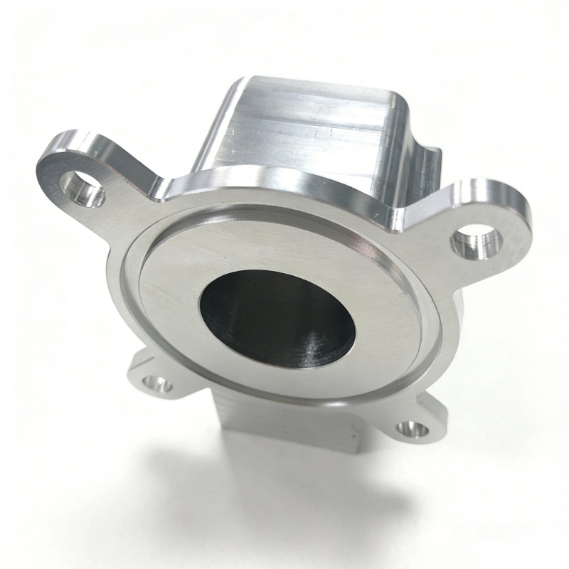
Aluminum Product Processing
Irregular Shaped Aluminum Parts - CNC Machining
CNC machining of asymmetric, free-form and thin-wall aluminium parts: five-axis where setups matter, process tabs for clamping, ±0.02 mm contour.
Product Details
"Irregular shaped part" is a description of the drawing, not of the machining problem. The problem is always one of two things: the part has features on faces that cannot all be reached in one orientation, or it has no natural surface to clamp on. Five-axis machining solves the first. Nothing solves the second except planning it into the part.
We machine irregular aluminium parts — asymmetric sections, irregular contours, free-form surfaces, polyhedra, thin-wall irregular parts — on five-axis and three-axis machining centres and gantry mills, to ±0.01–0.05 mm, with a repeat positioning accuracy of ±0.005 mm, contour accuracy of ±0.02 mm and surface roughness Ra ≤ 1.6 µm, on envelopes up to 6,500 × 550 × 500 mm.
When five axes is actually necessary
Five-axis machining is often specified because the part looks complicated. It is worth being precise about when it earns its cost.
| Part characteristic | Right machine | Why |
|---|---|---|
| All features reachable from one direction | Three-axis | Fewer setups than five-axis, faster, cheaper |
| Features on two or three faces, non-critical relative position | Three-axis with two or three setups | The setup error is smaller than the tolerance |
| Holes at multiple angles, position critical at ±0.02 mm | Five-axis, one setup | Multiple setups multiply the positioning error |
| Free-form surface with contour tolerance | Five-axis | The tool stays normal to the surface; a three-axis machine cannot at steep walls |
| Deep cavity with tapered or curved walls | Five-axis | Tool access without a long, deflecting overhang |
| Thin-wall part with features on both sides | Five-axis, if the wall cannot take a second clamping | Re-clamping a thin wall deflects it |
The rule that comes out of this: five-axis is justified when the cost of an extra setup exceeds the cost of the machine time. An extra setup costs a re-clamp, a re-datum and an accumulated error; on a part with a ±0.02 mm relationship between two faces, that error alone settles it.
On a part where the features are independent — a bracket with a hole on one face and a slot on another, neither position-critical to the other — three-axis with two setups is cheaper and just as good. Specifying five-axis there adds cost for no benefit.
The clamping problem, and the process tab
An irregular part often has no flat face to sit on and no parallel faces to grip. That is a design problem that has to be solved before machining, and the standard answer is a process feature.
Process tabs. Small bridges of material left between the part and the stock, holding it during machining and cut away at the end. They let the part be held from outside its finished envelope, so the clamp never touches a finished surface.
Sacrificial base. The part is machined from a block with an extra layer at the bottom, held on that layer, and the layer is faced off last. It works for a part with one flat side and needs the part to be thick enough to lose the layer.
Cast or extruded locating feature. If the part starts as an extrusion, the extrusion can include a boss or a rib that exists only for clamping and is removed in the last operation. This is a die-stage decision and it is the cheapest of the three when it is available.
Dedicated fixture with a conforming pocket. A fixture machined to the part's own shape, holding it on a large area rather than at points. Expensive to make and the right answer for a repeated part.
The choice is made from the drawing before the part is quoted. If a part has no clamping surface and no allowance for a tab, the quotation has to include one, or the part cannot be made to tolerance.
Thin-wall irregular parts: the deflection problem
A thin wall deflects under cutting force, and then springs back, so the cut is shallow in some places and deep in others. On an irregular thin-wall part this shows as a wall thickness that varies.
The controls:
- Support the wall from behind. A filler, a low-melting compound, or a fixture that contacts the wall over its area rather than at points.
- Reduce the radial cutting force. Sharp tools, high speed, light radial engagement, and a climb cut. The force that deflects the wall is the radial force, and it is controllable.
- Rough and finish separately. Rough with stock left, let the part relax, then finish. On a thin wall the relaxation between passes is significant.
- Machine symmetrically. Removing material from one side only moves the neutral axis and bows the part. Alternating sides keeps it balanced.
A reference of ±0.03 mm on wall thickness for a thin irregular cavity is achievable with all four, and is not achievable with any three.
Surface finish on a free-form contour
A curved surface machined with a ball-nose cutter leaves scallops between passes, and the height of the scallop depends on the step-over and the tool radius. Ra ≤ 1.6 µm is a normal machined finish; Ra ≤ 0.8 µm needs a tighter step-over, a smaller tool, or a finishing pass, and it costs time in proportion.
The practical point for a buyer: the surface roughness you specify on a curved face determines the machining time more than the tolerance does. Going from Ra 1.6 to Ra 0.8 on a large free-form surface can double the finishing time. Specify it only where it is functional — a sealing face, a sliding contact, an optical or visible surface — and leave the rest at the standard.
Specifications
| Item | Reference value |
|---|---|
| Equipment | Five-axis and three-axis machining centres, gantry mills, turn-mill centres |
| Machining accuracy | ±0.01 to ±0.05 mm |
| Repeat positioning accuracy | ±0.005 mm |
| Contour accuracy | ±0.02 mm |
| Surface roughness | Ra ≤ 1.6 µm standard; Ra ≤ 0.8 µm on request |
| Maximum envelope | 6,500 × 550 × 500 mm |
| Part types | Irregular sections, irregular contours, free-form surfaces, polyhedra, thin-wall irregular parts |
| Alloys | 6061-T6, 6063-T5, 6005-T6, 6082-T6, 7075-T5 |
| Surface treatment | Anodising, hard anodising, sandblasting, brushing, powder coating, conductive oxidation |
| Input | Drawing-based or sample-based |
| Minimum quantity | 50 kg |
| Sample lead time | 3–7 days, depending on complexity |
| Batch lead time | 7–15 days after sample approval |
| Standard | GB/T 6892-2023 high precision grade |
Matching the part to the machine
| Part type | Machine | The requirement that drives it |
|---|---|---|
| Robot arm curved surface | Five-axis | Contour ±0.02 mm and a good surface on a compound curve |
| Irregular section structural part | Three-axis plus dedicated fixture | Reliable clamping; full section features |
| Multi-angle mounting holes | Five-axis | All angles in one setup; hole position ±0.02 mm |
| Thin-wall irregular cavity | Three-axis plus support fixture | Deformation control; wall thickness ±0.03 mm |
| Free-form visible surface | Five-axis | Surface finish and contour together |
Note the second and fourth rows: three-axis with the right fixture is not a downgrade. On a part where the features are reachable from one direction, a three-axis machine with a rigid dedicated fixture holds a tighter wall thickness than a five-axis machine with an improvised clamp, because the deflection comes from the clamping, not from the axes.
Where it does not fit
- The part has no clamping surface and no allowance for a process tab. It cannot be held without deflecting. Add a tab or a sacrificial base at design stage — it is a drawing change, not a machining trick.
- The tolerance is ±0.01 mm on a dimension measured from an as-extruded surface. The extrusion tolerance is larger than the machining tolerance. Machine the datum surface first.
- The wall is very thin and the surface finish is tight. Ra 0.8 µm on a 1 mm wall is a deflection problem before it is a finish problem. Support the wall or relax one of the two requirements.
- The part is a one-off prototype and the geometry is still changing. A dedicated fixture is wasted. Consider a machined-from-solid approach with simple clamping, and accept a looser tolerance.
- You need a sample-based copy with no drawing. It can be done — we will reverse-model the part to a drawing first — but the tolerance is then set by the scan, not by an engineering requirement. Expect that to be documented.
- The part is large and irregular. The 6,500 × 550 × 500 mm envelope is the limit, and a large irregular part may exceed it in one direction. Check the envelope before quoting.
What to send for a quote
Send the 3D model and the drawing with the tolerances, the datum scheme, the alloy, the quantity, the surface finish per face, and the features that are functionally critical. Tell us how the part will be held in service, if that matters — a part that is clamped at four points in use may need to be machined in that condition to hold its shape.
We will reply with the machine selection and the reasoning, the clamping method including any process tab we would need, the number of setups, the achievable tolerances and surface finish, and the inspection plan. If the part cannot be held without deflecting, that goes in the reply before the program is written.
FAQ
What accuracy can you hold on an irregular part?
Reference ±0.01 to ±0.05 mm depending on the feature, with ±0.005 mm repeat positioning, ±0.02 mm contour accuracy and Ra ≤ 1.6 µm. Those are capability references: the value on your order is set by your drawing, and on an irregular part we also agree which datum the tolerance is measured from, because a tolerance referenced to an as-extruded surface is not the same requirement. We confirm both in writing before you order.
Do I need five-axis machining?
If the features are on multiple faces with a critical relationship, or if there is a free-form surface with a contour tolerance, yes. If the features are reachable from one direction or are independent of each other, three-axis with one or two setups is cheaper and just as accurate. Five-axis earns its cost by removing setups, not by being more precise.
How is an irregular part held?
With a process feature: tabs between the part and the stock, a sacrificial base, a dedicated fixture with a conforming pocket, or a locating boss that was designed into the extrusion. Without one of these, the part has to be clamped on a finished surface, which marks it and deflects it.
How is thin-wall deformation controlled?
By supporting the wall, reducing the radial cutting force with sharp tools and light engagement, roughing and finishing separately so the part can relax, and machining symmetrically so the neutral axis does not move. All four are needed; any three leaves the wall thickness out.
Can you work from a sample instead of a drawing?
Yes. We scan and reverse-model the part first, then machine from the model. The caveat is that the tolerance then comes from the scan and the model, not from engineering intent, and a worn or distorted sample will be reproduced with its defects. If the part is functional, a drawing is better.
What surface finish is realistic?
Ra 1.6 µm as standard on machined faces, Ra 0.8 µm on request. On a free-form surface the finish is controlled by the step-over, and tightening it from 1.6 to 0.8 can double the finishing time. Specify it where it is functional and leave the rest at standard.
How is it priced?
On the part volume removed, the number of setups, the fixture, the surface finish and the tolerance. Five-axis time and a dedicated fixture are the two big variables. A quote that does not mention the fixture is a quote that has not considered how the part will be held.
Send your drawing
Email the 3D model, the drawing with tolerances and the functional faces to linjunbing@truetrustlv.com, or send it on WhatsApp at +86 136 6644 0600. You will get a machine selection, a clamping plan and a written tolerance statement.
GET A QUOTE
Once you have submitted your requirements, we will contact you as soon as possible regarding your product inquiry.:Irregular Shaped Aluminum Parts - CNC Machining