
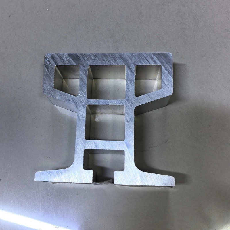
Aluminum Product Processing
RGV/AGV Track Profiles - Contact Pressure and Wear
An aluminium AGV track fails at the running surface, not in bending. Wheel contact pressure, hard anodising limits, joint steps and thermal expansion.
Product Details
An aluminium track for an RGV or an AGV is usually specified as a structural member: section modulus, deflection under load, straightness. All three matter, and none of them is what actually wears the track out. What wears it out is the contact between a hardened steel wheel and a rail whose surface is roughly a third as stiff and a quarter as hard as the wheel.
The failure is not a bend and not a crack. It is a row of shallow dents along the running surface — brinelling — each one a small impact for the next wheel that passes. Once the running surface is no longer smooth, the vehicle vibrates, the wheel bearings and the rail both degrade faster, and no amount of straightness tolerance helps.
We extrude and machine RGV and AGV track sections in 6061-T6, 6005-T6 and 6082-T6, with straightness of 0.2 mm/m, machined running surfaces to ±0.05 mm and joint steps controlled to a few hundredths of a millimetre, up to 6,500 mm per piece.
The rail is limited by contact pressure, not by bending
A steel wheel on an aluminium rail makes a line contact, and the peak pressure at that line is what the aluminium has to survive. It rises as the wheel load rises, as the wheel gets smaller, and as the contact gets narrower:
Take a 2,000 N wheel load on a 40 mm radius wheel with 25 mm of contact width. The peak contact pressure works out at roughly 190 MPa against a 6061-T6 yield of about 276 MPa. That is workable, with margin.
Now change the design without changing the load:
| Change | Peak contact pressure | Against 276 MPa yield | Consequence |
|---|---|---|---|
| Reference: R40, 25 mm wide, 2,000 N | ~190 MPa | 69 % | Stable running surface |
| Wheel radius reduced to 25 mm | ~240 MPa | 87 % | Marginal; local yielding at shock loads |
| Contact width halved to 12.5 mm | ~270 MPa | 98 % | Brinelling begins; running surface deforms |
| Wheel load raised to 4,000 N at R25, 12.5 mm | ~380 MPa | 138 % | Permanent dent each pass; track life in months |
The important reading is that a track can pass every bending calculation and still fail at the surface. The design levers, in order of effectiveness, are: larger wheel diameter, wider wheel face, more wheels sharing the load, and only then a harder rail surface. Halving the wheel radius raises the contact pressure by about 40 per cent; doubling the track's section modulus does nothing for it at all.
Hard anodising is a real answer with real limits
A hard anodic coating on 6061 gives a surface hardness in the region of 400 to 500 HV, against roughly 100 HB for the bare alloy, and it improves wear resistance dramatically. It is also brittle, and that is the trade:
- Wear resistance: excellent. Abrasion and sliding wear on the running surface drop sharply.
- Contact fatigue: limited. Under a high peak pressure the brittle coating cracks, and once cracked it spalls. A spalled patch is worse than an uncoated rail, because the edge of the spall is a step.
- Coating growth is dimensional. A 50 µm coating moves the surface about 25 µm, which has to be allowed for if the rail height is dimensioned.
- Masking is needed on any face that has to conduct, seal or fit precisely.
So hard anodising is the right answer where the contact pressure is moderate and the problem is sliding wear, and the wrong answer where the pressure is high enough that the coating will crack. Where both high load and wear protection are needed, a stainless or hardened steel wear strip fastened to the aluminium section is the more durable arrangement — the aluminium becomes the structure and the steel takes the contact.
Joint steps matter more than straightness
A track is supplied in lengths and joined on site. Every joint is a potential step, and a step is an impact that recurs at the vehicle's cycle rate. At 3 m/s, a 0.2 mm step is felt through the whole vehicle; a 0.5 mm step damages wheels.
What we do to make the joint closable:
- Machine the ends square and matched. The two mating ends of a joint are machined as a pair where possible, so the rail height and the running surface align even if the sections are not identical.
- Control the joint step, not just the cut. The drawing should state a maximum step at the running surface — 0.05 to 0.1 mm is realistic for a machined joint, and it is a different requirement from the section tolerance.
- Provide a joint feature. A tongue-and-groove, a dowel or a machined spigot makes the alignment a property of the parts rather than of the installer's skill.
- Allow for thermal movement. A 20 m track moving through a 15 °C swing expands by about 7 mm. If both ends are rigidly fixed, that movement becomes either a buckle or a joint that closes to zero gap and then loads the fasteners. One end floats, or the joints are designed with an allowance.
Fatigue: the track's real duty cycle
An RGV doing 60 cycles an hour runs about 500,000 cycles a year, and a busy AGV fleet does more. Aluminium has no true endurance limit, so the S-N curve keeps falling and the design has to be made against a cycle count, not against a single load case.
The details that decide the fatigue life are the ones that concentrate stress:
- Bolt holes in the track flange. Every hole is a stress raiser, and a row of holes along a bending member is a row of initiation sites. Fewer, larger fasteners usually outlast many small ones.
- The fastener itself. A bolt that is not preloaded slips under the cyclic load, and fretting at the joint face initiates cracks in aluminium quickly. Preloaded bolts with a controlled torque are a fatigue measure, not just an assembly preference.
- Welded brackets. A weld on a track is a fatigue detail with an allowable stress well below the parent metal, and the heat-affected zone on a 6xxx alloy runs at 50 to 65 per cent of parent strength.
- Section transitions. An abrupt change of section in a track is a stress concentration. A generous transition costs a little extrusion complexity and buys a lot of life.
Why aluminium rather than steel, and when not to
The case for aluminium is weight, corrosion and machinability. A track section in aluminium is roughly a third the weight of an equivalent steel section, which matters when the track is carried on a mezzanine, a ceiling structure or a moving gantry. It does not rust, it can be cut and drilled on site with hand tools, and it can be extruded into a shape that carries the guide feature, the rack, the cable channel and the mounting slots in one piece.
The case against is the one this page is about: contact pressure and wear. Where the wheel loads are high, the wheels are small, or the duty is millions of cycles, steel is the correct material for the running surface and aluminium is the correct material for the structure. A hybrid — aluminium section with a steel wear strip — is often the cheapest way to get both, and it is worth considering before the section is designed rather than after.
Specifications
| Item | Reference value |
|---|---|
| Alloys | 6061-T6, 6005-T6, 6082-T6 |
| Straightness | ≤ 0.2 mm/m |
| Machined running surface | ±0.05 mm; flatness per metre |
| Joint step at the running surface | 0.05–0.1 mm with a matched machined joint |
| Maximum length per piece | 6,500 mm |
| Typical wheel load | 1–3 kN per wheel; higher on request with a wear strip |
| Running surface treatment | Bare, hard anodised, or steel wear strip |
| Thermal expansion | 23.6 µm/m/K; 7 mm over 20 m for a 15 °C swing |
| Integrated features | Guide groove, rack teeth, cable channel, mounting slots |
| Inspection | Dimensional report, straightness, joint step measurement |
| Standard | GB/T 6892-2023 high precision grade |
Where it does not fit
- Heavy wheel loads on a small wheel. Above roughly 3 kN on a wheel under 30 mm radius, bare aluminium will brinell; the answer is a steel wear strip or a steel rail.
- Millions of cycles at high contact stress with a hard-anodised surface. The coating will crack and spall. Wear resistance and contact fatigue resistance are different properties and hard anodising buys only the first.
- Outdoor tracks with large temperature swings. The expansion has to be designed out with floating fixings; a rigidly fixed 20 m aluminium track will buckle or tear its anchors.
- Track that has to be perfectly level over a long run without adjustment. No extrusion is straight enough to install without shimming; the design should include an adjustment provision rather than a tighter tolerance.
- Very small quantities of a custom section. A die is a project; existing track sections or a machined profile are the answer for a prototype.
FAQ
What straightness and tolerance can you hold on a track?
Straightness ≤ 0.2 mm/m, machined running surfaces to ±0.05 mm, and a joint step of 0.05–0.1 mm where the ends are machined as a matched pair, in lengths up to 6,500 mm. Those are capability references: the value on your order is set by your drawing, and the achievable straightness depends on the section and how it is handled after extrusion. We confirm the achievable figures in writing before the die is cut.
Why is my aluminium track denting under the wheels?
Contact pressure, not load capacity. A small or narrow wheel concentrates the load until the peak pressure at the contact line approaches the alloy's yield strength, and the surface takes a permanent set on each pass. Larger wheels, wider wheel faces or more wheels sharing the load fix it; a thicker track section does not.
Is hard anodising enough for a running surface?
For sliding wear, yes. For high contact pressure, no: the coating is hard and brittle and will crack and spall under repeated high stress, which is worse than bare aluminium because a spall edge is a step. Where both load and wear are high, a steel wear strip is the durable answer.
How do you control the step at a joint?
By machining the two mating ends as a pair and controlling the joint step as its own requirement, separate from the section tolerance. Where the design allows, a dowel, a spigot or a tongue-and-groove makes the alignment a property of the parts rather than of the installation.
Do I need to allow for thermal expansion?
Yes, on anything over a few metres. Aluminium expands at 23.6 µm/m/K, so a 20 m track moves about 7 mm across a 15 °C swing. One end should float, or the joints should carry the allowance; both ends rigidly fixed is a buckling risk.
Can the guide groove and the rack be extruded into the section?
Yes, and it is the main reason to develop a die for a track. A guide groove held by the die costs nothing per part, and the rack teeth can be extruded too if the pitch is constant along the length. The limit is the die's tongue strength, which constrains how deep and how narrow the groove can be.
Send your drawing
Email the track section with the wheel load, wheel diameter and contact width, the cycle rate and the joint detail to linjunbing@truetrustlv.com, or send it on WhatsApp at +86 136 6644 0600. You will get a contact pressure check against the alloy, a recommendation on the running surface, and a written tolerance statement for straightness and joint step.
GET A QUOTE
Once you have submitted your requirements, we will contact you as soon as possible regarding your product inquiry.:RGV/AGV Track Profiles - Contact Pressure and Wear