
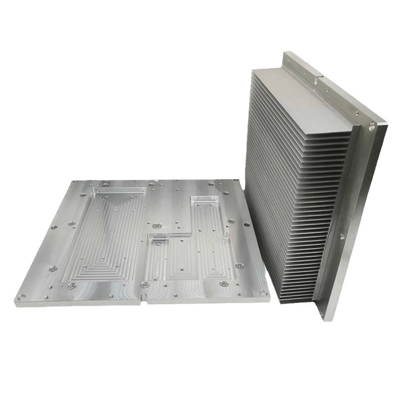
Aluminum Product Processing
Liquid Cooling Plate Profiles - Channel Route and Flatness
Four ways to make a cold plate, and the two places they fail: flatness over the channel after joining, and what the coolant does to the aluminium.
Product Details
The specification on a liquid cooling plate is usually written as a thermal one: flow rate, inlet temperature, thermal resistance. The manufacturing decision that sits underneath it is a different question entirely — how the channel is created — and that decision fixes the cost, the flatness, the leak risk and the maximum pressure long before any thermal calculation matters.
There are four ways to make an aluminium cold plate, and they are not interchangeable. Each produces a different channel geometry, a different joint, a different flatness and a different price curve against volume. This page sets out the four, and the two places where cold plates usually fail: the flatness of the face over the channel, and what the coolant does to the aluminium over five years.
We extrude cold plate sections and machine them, with friction stir welding for the lid where the channel geometry needs it, in 6061-T6 and 6063-T5, machined and faced to ±0.01 mm with flatness controlled across the channel area.
Four ways to make a channel, four different products
| Route | How the channel is made | Channel freedom | Best volume | The cost that dominates |
|---|---|---|---|---|
| A. Extruded multi-port | Channels are holes in the extrusion, running the full length; ends are closed with fittings or welded caps | Straight only; fixed cross-section | Medium to high | The die, amortised |
| B. Extruded base, milled channel, FSW lid | Channel milled into a flat extrusion, lid joined by friction stir welding | Almost any planar path: serpentine, parallel, manifold | Low to medium | Machining time and the FSW pass |
| C. Brazed sheet | Stamped plates with braze clad, joined in a vacuum or CAB furnace | Any planar path, thin sections | High | Tooling and furnace size |
| D. Machined and sealed | Channel milled into a plate, lid sealed with an O-ring or gasket | Any path, easy to prototype | Single pieces | Machining and the seal |
Route A is the cheapest per part at volume and the most restricted: the channel is whatever the die can flow, it runs straight from end to end, and the end closure becomes the leak-critical feature. Route B is the workhorse for anything with a serpentine or a manifold, because friction stir welding is a solid-state process and does not melt the lid, so the plate does not distort the way a fusion weld would. Route C is the automotive volume answer and needs a brazing furnace, which sets a minimum batch. Route D is for ten pieces and a deadline.
Friction stir welding is why route B works
A cold plate with a milled channel needs a lid, and a fusion-welded lid on a 5 mm plate will bow. The heat input is concentrated, the plate is thin relative to the weld, and the shrinkage pulls the face out of flat by more than the flatness tolerance the application needs.
Friction stir welding avoids that because the metal never melts. A rotating tool stirs the material at the joint at around 80 per cent of the melting temperature, forging the two surfaces together. The consequences that matter for a cold plate:
- Distortion is much lower than fusion welding, and the plate stays flat enough that a light facing pass afterward is enough.
- No filler metal and no porosity, so the joint has no cast structure and no gas pockets to leak through.
- The joint is a solid-state bond, so it does not have the heat-affected-zone softening that a fusion weld produces — typically 50 to 65 per cent of parent strength on a 6xxx alloy.
- The tool needs access along the whole joint line, and it leaves a keyhole at the end of the run, which has to be placed outside the sealed region or plugged.
One constraint that catches people: the lid must be a flat plate with a straight tool path. A serpentine channel is fine under a flat lid; a channel that needs the lid to bend around a feature is not an FSW job.
Flatness over the channel is the real specification
A cold plate is clamped against a heat source through a thermal interface. What conducts is the interface, and the interface is only as good as the flatness of the two faces. Over a channel, the wall between the coolant and the component is thin by design — that is how the thermal resistance is kept low — and a thin wall over a pressurised channel is the least flat part of the plate.
What we hold and what it costs:
| Requirement | What it implies | Effect on cost |
|---|---|---|
| Flatness 0.10 mm over the channel area | Achievable after FSW with a light facing pass | Baseline |
| Flatness 0.05 mm over the channel area | Facing after joining, with the plate stress-relieved first | Adds a machining operation and a handling step |
| Flatness 0.02 mm over the channel area | Facing with the plate on a supported fixture, measured at temperature | Significant; often the dominant cost |
| Flatness specified over the whole plate | Usually unnecessary; state it over the contact footprint | Can double the price for no benefit |
The specification worth writing is the flatness over the contact footprint at operating temperature, not over the whole plate at 20 °C. A plate that is flat cold and bowed hot is not a flat plate, and with a 100 mm wide part a 20 °C rise moves things by about 0.05 mm — the same order as the tolerance being argued about.
Coolant chemistry is a materials decision
Aluminium and water are not a stable couple. Aluminium forms a passive oxide layer that protects it in neutral water, but that layer breaks down in the presence of chloride, copper ions or the wrong pH, and once it breaks down the corrosion is localised and fast. Three things follow, and they are routinely ignored:
- Use a formulated coolant, not water. An inhibited glycol or a proprietary coolant with a corrosion package. The inhibitors are what keep the oxide layer intact; plain water, or water topped up from a tap, is what destroys the plate in two or three years.
- Do not mix metals in the loop without thinking. A copper cold plate and an aluminium one on the same circuit create a galvanic couple, and the aluminium becomes the anode. If the loop has copper anywhere, the aluminium needs protection and the coolant needs monitoring.
- Brazed plates have a specific risk. The braze clad is a 4xxx alloy with silicon, which is cathodic to the core, and the joint region is where corrosion starts. Vacuum brazing leaves no flux residue; a flux-brazed plate that was not properly rinsed leaves chloride behind, which is worse than no coating at all.
Pressure, and what it is actually limited by
A cold plate is usually specified at 0.3 to 0.5 MPa working pressure with a proof test above that and a burst requirement of roughly three times working. The limit is not the aluminium; it is the joint. An FSW joint or a braze joint is a fraction of the parent metal's strength in peel, and a channel is a pressure vessel in the worst orientation for a lap joint — the pressure tries to peel the lid off, not to shear it.
Two design rules follow: keep the channel width modest relative to the wall, because burst pressure falls with the square of the span; and put the retaining geometry — a step, a groove, a mechanical interlock — where the pressure can load it in shear rather than peel.
Flow distribution: where the hot spot comes from
A parallel-channel plate with a manifold at each end promises even flow to every channel. It does not deliver it, because the manifold is a pressure gradient: the channel nearest the inlet sees a higher pressure difference than the channel at the far end, and takes more flow. The result is a cold region near the inlet and a hot region at the far end, on a plate that was designed to be uniform.
The controls are geometric, and they belong in the design rather than in the machining:
- Shorten the manifold or feed it from the centre, so the pressure difference between channels is small relative to the channel pressure drop.
- Add restriction deliberately — a smaller inlet to each channel makes the channel's own resistance dominate the manifold's imbalance.
- Use a serpentine where uniformity matters more than pressure drop. A series path guarantees every element sees the same flow, at the cost of a much higher total pressure drop.
- Accept the gradient where the heat load has the same gradient. A plate cooling a row of devices with the hot end at the outlet is often arranged correctly by accident.
Specifications
| Item | Reference value |
|---|---|
| Alloys | 6061-T6 standard; 6063-T5 for extruded multi-port sections |
| Channel routes | Extruded multi-port; milled channel with FSW lid; brazed; machined and sealed |
| Joining | Friction stir welding; vacuum or CAB brazing through partners |
| Machining tolerance | ±0.01 mm on features; flatness stated over the contact footprint |
| Typical flatness | 0.10 mm standard after joining; 0.05 mm with a facing pass; 0.02 mm on request |
| Maximum machined length | 6,500 mm |
| Leak test | Pressure decay or helium, per drawing |
| Typical working pressure | 0.3–0.5 MPa, with proof and burst per specification |
| Coolant compatibility | Inhibited glycol or formulated coolant; not untreated water |
| Surface treatment | Anodising, chromate-free conversion coating, or bare |
| Standard | GB/T 6892-2023 high precision grade |
Where it does not fit
- Channel geometry that is not planar. All four routes produce a channel in one plane. A channel that has to wrap a corner is a machined or cast part, not a plate.
- Working pressures above about 1 MPa. Achievable with thicker walls and a better joint, but the weight advantage over a brazed steel or a cast plate disappears, and the joint becomes the design driver.
- Untreated water as the coolant. We will not design a plate for a loop that will run on tap water and expect it to last; the failure mode is predictable and it is not covered by any tolerance.
- Very low volume with a serpentine channel. Route B needs a machining programme and an FSW setup; at ten pieces, route D with a gasket is usually cheaper.
- Plates where the flatness is specified cold and the part runs hot. The number that matters is at operating temperature, and a cold measurement will not predict it.
FAQ
What flatness can you hold on a cold plate?
0.10 mm over the channel area after joining as standard, 0.05 mm with a facing pass on a stress-relieved plate, and 0.02 mm on request with a supported fixture and measurement at temperature. Those are capability references: the value on your order is set by your drawing, and the achievable figure depends on the channel width, the lid thickness and the joining method. We confirm the achievable value in writing before the plate is made.
Extruded multi-port or milled channel with FSW?
Extruded if the channel can be straight and the section can carry it: no weld, lowest cost at volume, best pressure capability for a given wall. Milled with an FSW lid if the channel has to be serpentine, manifolded or varied along the length. The die cost decides the crossover, which is usually a few thousand pieces.
Why does my plate bow after joining?
Heat input and differential shrinkage, or residual stress in the plate being released as material is removed. FSW reduces the first; the second is addressed by facing after joining rather than before, and by relieving the plate before the final cut. A plate faced flat and then welded will not stay flat.
Can I run plain water in it?
Not for a service life measured in years. Aluminium needs an inhibited coolant to keep its passive oxide layer intact; untreated water, especially with chloride or mixed with copper in the same loop, will pit the channel. The plate will pass a leak test when it ships and fail in service, which is the worst possible outcome.
What is the maximum size?
6,500 mm in length on a milled and FSW plate, subject to the welding equipment's reach along the joint. Brazed plates are limited by the furnace, and extruded multi-port sections by the die and press.
Do you leak test?
Yes — pressure decay or helium, to the value on the drawing, with the result recorded against the batch. For a cold plate the leak test is the acceptance criterion that matters most, and it should be specified with a pressure, a duration and an acceptable decay rate rather than as "leak tight".
Send your drawing
Email the plate drawing with the channel layout, the working pressure, the flatness requirement and the contact footprint to linjunbing@truetrustlv.com, or send it on WhatsApp at +86 136 6644 0600. You will get a route recommendation with the reason, a note on where the flatness requirement lands after joining, and a written tolerance statement.
GET A QUOTE
Once you have submitted your requirements, we will contact you as soon as possible regarding your product inquiry.:Liquid Cooling Plate Profiles - Channel Route and Flatness