
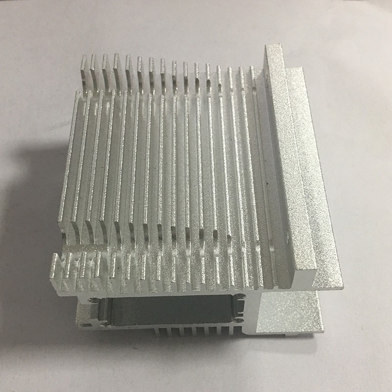
Aluminum Product Processing
High-Density Fin Heat Sink Profiles - Die Feasibility
The limit on fin density is the die tongue, not the heat transfer. Tongue stiffness falls with the cube of fin height, and why taller fins stop paying.
Product Details
A thermal engineer specifies a heatsink section by its performance: fin height, fin pitch, base thickness. A die engineer reads the same drawing and sees a row of thin steel tongues standing in a press with molten aluminium flowing past them at 450 °C. Those two views are compatible up to a point, and past that point the thermal drawing is simply not producible — not at any price, and not by any supplier.
This page is about that boundary. We develop dies for high-fin-count heatsink sections and supply the extrusions with the machining and finishing that follows, in 6063-T5 and 6061-T6, with fin thickness typically 0.8 to 1.5 mm and sections up to a 600–700 mm circumscribed circle.
The fin is a cantilever, and the die knows it
Inside a porthole die, each gap between two fins is formed by a tongue of tool steel that is supported only at its base. Aluminium flowing past it exerts a lateral force, and the tongue bends like any cantilever: deflection is proportional to the cube of its length.
That single relationship explains almost everything about high-density fin production:
| Fin height | Relative tongue stiffness | Fin thickness consistency | What it takes to produce |
|---|---|---|---|
| 10 mm | Reference | Good | Standard flat die, normal speed |
| 20 mm | About 1/8 | Fair | Porthole die, reduced speed |
| 30 mm | About 1/27 | Thickness varies along the height | Die flow balancing, slower still |
| 40 mm | About 1/64 | Visible taper; fins lean | Support bridges, careful bearing design |
| 60 mm | About 1/216 | Difficult to hold at all | Special design, multiple die corrections, low yield |
The consequence a customer feels is not a bent fin — the die is corrected until the section is straight. It is that the fin comes out tapered: thicker at the root, thinner at the tip, because the tongue deflects more where it is unsupported. A drawing that specifies 1.0 mm ±0.05 mm fin thickness over a 40 mm tall fin is specifying something the process cannot hold uniformly, and the tolerance has to be stated at the tip, at the root, or as an average.
Fin pitch: the limit is the tongue, not the heat transfer
Thermally, denser fins are better until the air stops flowing between them. Mechanically, the limit arrives much earlier:
| Fin pitch | Fins per 100 mm | Die risk | Practical consequence |
|---|---|---|---|
| 8–10 mm | 10–12 | Low | Robust, long die life, easy to clean |
| 5–6 mm | 16–20 | Moderate | Standard high-density work |
| 3–4 mm | 25–33 | High | Thin tongues, frequent die correction, short die life |
| 2–2.5 mm | 40–50 | Very high | Feasible only at low fin height and in a forgiving alloy |
| Below 2 mm | > 50 | Not commercial | Tongues too slender to survive; not produced by extrusion |
The combination that fails first is high and dense. A 50 mm tall fin at 2 mm pitch is a tongue 50 mm long and 1 mm thick with 1 mm of aluminium on each side — it will not survive a production run. A 15 mm tall fin at 2 mm pitch is a different proposition entirely and is produced routinely. So fin density and fin height trade against each other, and a thermal design that needs both is a design that needs a different process.
Why taller fins stop paying anyway
There is a second reason not to push fin height, and it comes from the heat transfer rather than the die. A fin is only as useful as its average temperature, and a tall thin fin runs cooler at the tip than at the root, so the tip contributes less. The fin efficiency falls as the fin gets taller:
| Fin height (1.0 mm thick, natural convection) | Fin efficiency | Area index (efficiency × area) |
|---|---|---|
| 20 mm | About 0.97 | 4.8 |
| 40 mm | About 0.87 | 8.7 |
| 60 mm | About 0.75 | 11.2 |
| 80 mm | About 0.64 | 12.7 |
| 100 mm | About 0.54 | 13.6 |
Doubling the fin height from 40 to 80 mm adds about 47 per cent to the useful area, not 100 per cent, and it costs a much harder die and a heavier part. Past roughly 60 mm the return on additional height is small enough that a wider section, a forced-air design or a different cooling method usually wins. The thermal argument and the die argument point in the same direction, which is convenient.
The base is where most of the resistance hides
Heatsink discussions concentrate on fins, and the base is where the design is usually wrong. Heat enters through a small footprint — a chip, a MOSFET, a die — and has to spread sideways through the base before it reaches the fins. That spreading resistance depends on the base thickness and the base area, and on a section with a thin base it can be larger than the entire fin resistance.
Three practical rules we apply when reviewing a heatsink section:
- Base thickness should be at least a third of the heat source's largest dimension, and more where the source is small relative to the section.
- A thick base is cheap to extrude. Adding 2 mm to a base costs far less than adding 10 mm to fin height, and often does more for the total thermal resistance.
- Interface matters more than metal. A 0.1 mm air gap under a power device is a worse thermal problem than any fin geometry choice, and it is solved by flatness and a proper interface material, not by a denser fin.
What the die needs from the drawing
A heatsink section that will be produced well is one that gives the die a chance. Five things we ask for, and that are often missing:
- Fin thickness stated with where the tolerance applies. Root, tip, or average. A single figure with a tight tolerance on a 40 mm fin is not measurable in a way that matches the process.
- Fillet radius at the fin root. A sharp root is a stress concentration in service and a die wear point in production. A root radius of 0.5–1.0 mm is normal and costs nothing thermally.
- Symmetry, where the application allows it. A symmetric section flows evenly and holds tolerance; a section with fins on one side of a heavy mass requires flow balancing that is corrected by hand on the die.
- An agreed datum for the mounting face. Flatness is specified on the mounting face, and the extrusion is straightened against it, so the drawing has to say which face that is.
- Whether the fins will be milled after extrusion. A section that is going to be skimmed or slotted is extruded with stock, and the fin tolerances can then be relaxed at the press.
Die life, and why the price per metre moves
A high-fin-count die is consumable. It is corrected, nitrided, corrected again, and eventually retired. The number of metres it produces before retirement depends on the fin aspect ratio and the alloy, and it is the reason two heatsink sections of the same weight can differ substantially in unit price.
What this means commercially:
- Die cost is a per-project cost, amortised over the order. A dense section at low volume carries a high die cost per part; the same section at high volume is competitive.
- Repeat orders reuse the die, which is why a second order of the same section is materially cheaper than the first.
- Small design changes are not free. Moving a fin by 0.5 mm is a new die, not an adjustment. Changes should be batched before the die is cut.
The die belongs to the project, not to the order
Where a customer expects to run a section for years, the die should be treated as an asset with a service life, not as a one-off purchase. That means recording how many metres it has run, when it was last nitrided, and what its current fin thickness measures at the tip. A die that is allowed to wear produces sections that drift out of tolerance slowly, and the drift is invisible until an assembly stops fitting.
Specifications
| Item | Reference value |
|---|---|
| Alloys | 6063-T5 standard; 6061-T6 where strength or hardness is needed |
| Fin thickness | 0.8–1.5 mm typical |
| Fin height | Up to about 60 mm, depending on pitch |
| Fin pitch | Down to about 2 mm at moderate height |
| Fin thickness tolerance | Stated at root, tip or average; typically ±0.05 mm at the root |
| Extruded section tolerance | ±0.02 to ±0.04 mm on controlled dimensions |
| Maximum circumscribed circle | 600–700 mm |
| Straightness | ≤ 0.2 mm/m, referenced to the mounting face |
| Machining | Face milling of the mounting face, slotting, drilling and tapping to ±0.01 mm |
| Maximum machined length | 6,500 mm |
| Surface treatment | Clear or black anodising, hard anodising, sandblasting |
| Standard | GB/T 6892-2023 high precision grade |
Where it does not fit
- Fin pitch below about 2 mm. Not produced by extrusion. Bonded fin stacks, skived heatsinks or machined pin fins are the processes for that density.
- Tall and dense at the same time. A 50 mm fin at 2 mm pitch is beyond what a die tongue survives; one of the two numbers has to move.
- Sections that need fins on several faces at high density. Each face needs its own tooling approach and the flow balance becomes the limit, not the fins.
- Copper or aluminium-copper hybrids. Different process entirely; we extrude aluminium.
- Very low volumes of a dense section. The die cost dominates, and a machined or skived heatsink from standard stock is often cheaper for a hundred pieces.
FAQ
How dense a fin pattern can you produce?
Down to roughly 2 mm pitch at moderate fin height, with fin thickness typically 0.8–1.5 mm. Above about 30 mm of fin height the practical pitch opens up, because the die tongue has to survive the run. Those are capability references: the value on your order is set by your drawing, and the achievable combination of height and pitch is confirmed in writing when the die is reviewed, before it is cut.
Why is my fin thinner at the tip than at the root?
Because the die tongue deflects under the flow pressure, and it deflects most where it is least supported — at the tip. The effect grows with the cube of fin height. The die is corrected to bring the fin back to nominal, but on a tall fin a small taper usually remains, which is why the tolerance should be stated at a defined position rather than as a single figure.
Would a denser fin pattern improve cooling?
Only up to the point where the air can still pass between the fins, and the improvement per added fin falls quickly. Past about 60 mm of fin height the efficiency drop cancels most of the added area, and denser fins on a natural-convection heatsink often perform worse because the boundary layers merge and the air stops moving.
Can the fins be milled instead of extruded?
Yes, and for low volumes or unusual patterns it is the right route: a standard block is machined or skived into fins. It costs more per part than an extrusion and has no die cost, so it wins below a few hundred pieces and loses above a few thousand.
What alloy is best for a heatsink?
6063-T5 for almost everything: it extrudes well, finishes well and its thermal conductivity of around 200 W/m·K is close to the best available in a 6xxx alloy. 6061-T6 is used where the section must be stronger or harder, at some cost in extrudability and a small cost in conductivity.
Does anodising affect the thermal performance?
Slightly, and usually in the right direction. A thin anodic coating adds a small thermal resistance but raises the surface emissivity substantially, which helps radiation. On a natural-convection heatsink the net effect is typically neutral to positive; on a forced-convection heatsink it is negligible. Black anodising is preferred where radiation matters.
Send your drawing
Email the section drawing with the fin height, pitch, thickness and where the tolerance applies, plus the heat source footprint and the cooling method, to linjunbing@truetrustlv.com, or send it on WhatsApp at +86 136 6644 0600. You will get a die feasibility review, a note on which dimensions the process can hold and where they should be measured, and a written tolerance statement.
GET A QUOTE
Once you have submitted your requirements, we will contact you as soon as possible regarding your product inquiry.:High-Density Fin Heat Sink Profiles - Die Feasibility