
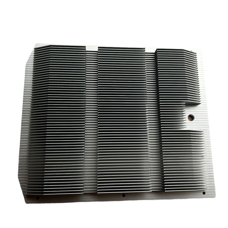
Aluminum profiles for radiators
Industrial VFD Heat Sink Aluminum Profiles
VFD heat sink profiles, one-piece extruded fins at 201 W/m-K, base flatness 0.05 mm per 100 mm, fin thickness ±0.03 mm. Section and tolerance per drawing.
Product Details
Short answer: a VFD heat sink is a one-piece extruded profile with the fins formed by the die, machined flat on the base and drilled for the IGBT module. The design case is not peak output, it is continuous duty: a drive that runs 24/7 for a decade accumulates thermal cycles that an assembled heat sink cannot survive without its interface degrading. We run 6063-T5 at about 201 W/m·K, hold base flatness at ≤ 0.05 mm/100 mm and fin thickness within ± 0.03 mm, in single extrusions up to 20 m. Section and tolerance are confirmed against your drawing.
What a drive duty actually demands
Most heat sink specifications are written around a maximum temperature, which is the right question for a device that runs hard for minutes. A variable frequency drive is the opposite case: it runs at moderate load for years, in a cabinet, often in a plant that is warm and dusty. The failure that matters is not a single overheating event but the slow accumulation of thermal cycling and the drift of every interface in the stack.
That changes what a heat sink has to be good at. Peak thermal resistance matters less than stable thermal resistance. A sink that measures well on the first day but whose interface degrades over 20,000 cycles will cause the drive to derate in year four, and derating is a real commercial loss: the drive no longer delivers its rated current, the machine it runs loses torque, and the customer reports a fault that the drive itself is not causing.
This is the argument for a one-piece extrusion over an assembled sink. An assembled heatsink joins fins to a base, either by inserting them into grooves or by bonding, and each of those joints is a thermal interface. Thermal interface resistance is not constant: the materials on either side expand at different rates, the joint oxidizes, and the contact pressure relaxes over time. The result is a resistance that climbs slowly, invisibly, and only shows up as a temperature rise that nobody associates with the heat sink. A one-piece extrusion has no such joint, because the fin and the base are the same piece of metal formed in one pass.
Specifications
| Item | Range |
|---|---|
| Construction | One-piece extrusion; fins, base and mounting features formed by the die |
| Alloy | 6063-T5, thermal conductivity about 201 W/m·K |
| Fin structures | High-density fin, multi-fin, comb-fin, or as drawn |
| Minimum fin thickness | 0.5 mm |
| Maximum fin height | 60 mm |
| Fin thickness tolerance | Reference ±0.03 mm |
| Base flatness | Reference ≤ 0.05 mm per 100 mm |
| Integrated features | Mounting holes and positioning slots extruded in place, reducing secondary machining |
| Single extrusion length | Up to 20 m, for multi-unit continuous sinks |
| Surface treatment | Natural or black anodizing, powder coating, as specified |
| Reference standard | GB/T 6892-2023, high-precision grade |
| Deep processing | CNC base milling, drilling and tapping, precision cut to length, chamfering and deburring |
Flatness and fin tolerance control two different things
Both numbers appear on the drawing and both are usually copied from a previous project without the reasoning behind them. They govern separate problems.
Base flatness controls the path from the IGBT module into the sink. The module is mounted on thermal interface material, and the layer thickness is set by how flat the base is. At ≤ 0.05 mm per 100 mm the layer stays thin and uniform, so the interface resistance is what the material datasheet promises. A base that is bowed forces a thicker layer at the edges, and on a module that switches hundreds of amps the resulting temperature difference across the module is enough to unbalance the current sharing between parallel IGBTs. That is a reliability problem, not just a thermal one.
Fin thickness tolerance controls the fin array itself. At ± 0.03 mm, the gaps between fins stay consistent along the length, so the airflow sees a uniform channel instead of a series of narrow and wide slots. On a forced-convection sink that means the flow distributes as designed rather than finding the widest gaps. On a natural-convection sink it matters differently: fin thickness is the conduction cross-section from the base to the tip, so a locally thin fin runs hotter at the top, and the fin spacing has to be wide enough that the boundary layers on adjacent fins do not merge and choke the chimney effect.
Extruded mounting features, and where they stop
Holes that are formed by the die rather than drilled save a machining step and eliminate a burr on the air side. For a positioning slot or a through-hole whose location only needs to be approximate, an extruded feature is the cheaper answer and it is dimensionally stable along the whole length.
The limit is tolerance. An extruded hole is not a machined hole: the die wear, the extrusion speed and the cooling all move it by more than a drilled feature would. Where a hole locates something precisely, or has to take a thread, it is extruded as a pilot and then machined. This is worth stating on the drawing, because the difference between "hole formed in extrusion" and "hole drilled after extrusion" is a line item the quotation has to reflect.
Long single extrusions up to 20 m are useful in a different way: a drive cabinet with several modules in a row can use one continuous sink rather than a series of short ones, which removes the joints between them and keeps the fin array uninterrupted. Transport and handling usually set the practical limit, not the press.
Where this fits
- General-purpose and vector VFDs in cabinets, where continuous duty and stable thermal resistance matter more than peak figures
- Servo drives and industrial power supplies with a similar continuous profile
- Multi-module cabinets that benefit from a single continuous sink instead of repeated short ones
- Installations in warm, dusty plants where an assembled sink's interface would degrade faster
- Designs where mounting holes and slots can be integrated into the extrusion to avoid secondary operations
Where it does not fit
- Very high power density where the required fin aspect ratio cannot be extruded, and a bonded or skived sink is needed.
- Small volumes where the die cost is not recovered, and a machined sink from plate is the cheaper route.
- Applications needing a heat pipe or vapor chamber embedded in the base, which cannot be formed in an extrusion.
- Layouts where the airflow direction is not along the fins. An extruded fin array has one direction; cross flow over it is close to useless.
What to send for a quote
- The module outline and mounting pattern, plus the module's power loss rather than its current rating
- The available space in the cabinet, including the airflow direction and whether it is forced or natural
- The ambient temperature inside the cabinet, which is always higher than the room
- The base flatness and fin tolerance you need, or the thermal resistance target they serve
- Which features can be extruded and which must be machined
- Quantity and the required length, checked against the 20 m extrusion limit
If the thermal design is not done, send the module datasheet and the cabinet constraints. Section and fin geometry can be proposed from the loss figure and the available airflow, and the estimate of base temperature comes with it.
FAQ
What flatness and fin tolerance can you hold?
As a reference, base flatness ≤ 0.05 mm per 100 mm and fin thickness deviation ± 0.03 mm. Both are achievable on 6063-T5 sections within the 0.5–60 mm fin range, and both move with fin density and section width: a very dense fin array is harder to hold than an open one. The value on your order is set by your drawing, and the figure we can confirm for your section is stated before production. If the thermal design needs tighter flatness than the section allows, that is raised at quotation rather than at first article.
Why is a one-piece extrusion better than an assembled heat sink?
Because it has no thermal interface between the fins and the base. An assembled sink's joint has a resistance that starts low and climbs over years as the joint oxidizes and the contact pressure relaxes. On a drive that runs continuously, that drift is the difference between holding rated output and derating in year four. The extrusion removes the mechanism instead of specifying a better joint.
Can the mounting holes be formed in the extrusion?
Positioning slots and approximate through-holes can. Anything that locates precisely or takes a thread is extruded as a pilot and then machined, because extrusion tolerance is looser than drilling. Stating on the drawing which is which keeps the quotation honest.
What fin height and density are practical?
From 0.5 mm minimum fin thickness up to 60 mm fin height, with the aspect ratio limited by the die rather than by the press. Denser and taller fins raise the surface area but narrow the air gap, and past a point the boundary layers merge and the extra area stops working. The useful density depends on whether the sink is forced or natural convection, which is why the airflow has to be known before the section is chosen.
Will the sink work in a sealed cabinet?
Only if the heat leaves the cabinet by another route. A sealed enclosure has no airflow to carry heat away from the sink, so the sink raises the internal air temperature rather than rejecting the heat. In that case the thermal path has to go through the cabinet wall, and the sink design changes completely. This is worth raising early, because a sink optimized for open airflow is the wrong part for a sealed box.
What surface treatment is usual?
Natural anodizing for corrosion protection with the metal visible, black anodizing where radiation matters or where the cabinet interior should be dark. Anodizing adds a very thin oxide that has slightly lower conductivity than the metal, which is negligible at these thicknesses but worth knowing if the design is already at its limit.
Send your drawing
Email linjunbing@truetrustlv.com with the module datasheet, the cabinet space and the airflow direction. If the thermal design is open, send the power loss and the ambient. You will get a section proposal, a quotation and the flatness we can hold — reviewed by an engineer, not an auto-reply.
WhatsApp: +86 136 6644 0600
GET A QUOTE
Once you have submitted your requirements, we will contact you as soon as possible regarding your product inquiry.:Industrial VFD Heat Sink Aluminum Profiles