
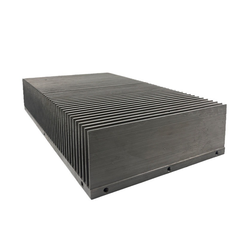
Aluminum profiles for radiators
High-Fin Air-Cooled Heat Sink Aluminum Profile
High fin air cooled heat sinks: fins to 60 mm tall, 0.5 mm thick, 15:1 ratio, 40% more area, flatness 0.05 mm per 100 mm. Geometry per drawing.
Product Details
Short answer: a high-fin air-cooled heat sink is an extruded profile with tall, thin, closely spaced fins that raise surface area inside a fixed footprint. Working reference: fins down to 0.5 mm thickness, up to 60 mm tall, at a height-to-thickness ratio of 15:1, thickness held within ±0.03 mm with no collapsed or starved fins, base flatness 0.05 mm per 100 mm. The area gain over a conventional profile is roughly 40 percent. Fin geometry is set by your drawing and your airflow.
What it is used for
It goes into air-cooled equipment where the heat load has grown but the enclosure has not: AI inference servers, GPU workstations, edge computing boxes, telecom remote units, industrial PCs, power supplies and test instruments.
Air cooling is still the default in these systems, for the practical reason that it needs no coolant loop, no pump and no service interval. What changed is the power. A chip that used to run at 150 W now runs at 400 W or more in the same 1U or 2U height, and a conventional fin stack runs out of surface before the fan runs out of capacity.
High-fin sections exist to close that gap. Taller, thinner, tighter fins put more area into the same base footprint, and the measured effect is a chip temperature 5 to 8 °C lower at equal power. That is enough to change a throttle threshold or a fan curve.
Specifications
| Item | Working reference | How it is set |
|---|---|---|
| Alloy | 6063-T5, about 201 W/m·K, from primary ingot | Chosen against your load case |
| Fin thickness | Down to 0.5 mm | Set by your drawing |
| Fin height | Up to 60 mm | Set by your enclosure |
| Fin height to thickness | Up to 15:1 | Set by your drawing |
| Fin thickness tolerance | ±0.03 mm | Set by your drawing |
| Base flatness | ≤0.05 mm per 100 mm | Set by your drawing |
| Fin straightness | ≤0.3 mm per meter | Set by your drawing |
| Surface area gain | About 40 percent over a conventional section | Result of the geometry |
| Heat relief | Two-stage constant-temperature aging | Process step, not optional on tall fins |
How it is made
- A die is cut for the fin geometry, and the metal flow is simulated before the die is made, because a 15:1 fin that starves cannot be fixed by adjusting the press.
- Extrusion runs with controlled billet temperature and speed, so the fins fill evenly along the length instead of tapering from head to tail.
- Two-stage constant-temperature aging follows, which releases residual stress. This is what keeps a base flat after the fins have cooled unevenly.
- The base is machined flat and the mounting features cut on the same datum, then deburred at the fin roots.
- Inspection checks fin thickness, fin straightness and base flatness on the finished part, plus a visual check for collapsed fins.
Where this fits
It fits when the enclosure height is fixed, the airflow is known, and the heat load has outgrown a standard section rather than outgrown air cooling altogether.
Where it does not fit: if the load needs a cold plate, tall fins will not rescue it and the system should move to liquid. If the available airflow is weak, a taller denser stack can perform worse than a shorter open one, because the fins resist the flow that is supposed to cool them. And if the profile is only needed in a few pieces, the die cost rules it out.
Three things people get wrong about tall fins
Fin efficiency falls as fins get taller. A fin is a conductor, not an isothermal surface. Heat enters at the root and has to travel up the fin, so the tip is always cooler than the base, and the effective area is less than the geometric area. At 60 mm tall on 0.5 mm thickness, a large part of the tip does far less work than the root. This is why doubling the fin height never doubles the performance, and why a design that keeps adding height eventually adds weight and cost for a degree or two.
Density trades against airflow. Tighter spacing adds area and adds resistance at the same time. A fan works on a curve: raise the resistance and the operating point moves to lower flow. Past a certain pitch the extra area is fed by less air, and the net result flattens or reverses. There is an optimum pitch for a given fan and duct, and it is not the tightest one the die can produce. This is the single most useful thing to settle before a section is drawn, and it needs the fan curve rather than only the heat load.
Residual stress decides the interface, not the fins. A high-fin section has very different wall thickness between the 0.5 mm fins and the base. It cools unevenly, so it carries stress. Machine the base without relieving that stress and it bows, the interface material has to bridge a gap, and the contact resistance eats the gain the fins were bought for. Two-stage constant-temperature aging is the process answer, and it is the reason a cheap high-fin profile often measures well on the bench and poorly in the assembly.
Where the aluminum comes from matters too. Primary ingot keeps the iron and silicon content low. Scrap-based billet carries those elements up, and iron in particular forms intermetallic phases that reduce conductivity and make thin fins harder to fill. The effect is not dramatic on a single part, but it makes thermal performance vary between lots, which is a problem when a customer has qualified a design at a stated temperature.
What to send for a quote
- The available footprint and height, and the section drawing if it exists
- Heat load in watts and the maximum allowed chip temperature
- The fan curve or the airflow available, since it sets the optimum fin pitch
- Mounting method, and whether the base is also a structural plate
- Quantity per year, because the die cost has to be amortized over it
FAQ
What fin geometry can you hold?
Fins down to 0.5 mm thickness, up to 60 mm height, at 15:1 aspect ratio, with thickness within ±0.03 mm and a base flatness of 0.05 mm per 100 mm. The value on your order is set by your drawing, and where a geometry pushes against the extrusion limit we say so before the die is cut rather than after the first sample.
How much cooler will my chip run?
Our reference figure is 5 to 8 °C lower than a conventional section at equal power, from the roughly 40 percent area gain. Your actual result depends on the airflow, the interface and the spreading in the base, so it is a design estimate rather than a guarantee. The value we commit to is the geometry on your drawing.
Can the fins be taller than 60 mm?
Beyond that ratio the fin efficiency drops enough that the extra area does little, and the die risk rises. If the load needs more than a 60 mm stack delivers, the honest answer is usually a different cooling approach rather than a taller fin.
Why does base flatness matter so much on an air-cooled part?
Because the heat still has to get into the base first. A bowed base needs a thicker interface layer, and at the heat flux of a modern chip that layer is a significant part of the total resistance. The fins cannot compensate for a bad interface.
Do you use primary aluminum?
Yes, A00 primary ingot for these sections. It keeps iron and silicon low, which protects conductivity and makes the thin-fin extrusion more stable from lot to lot. It costs more than scrap-based billet and it is the reason the thermal result repeats.
Can you machine the mounting features as well?
Yes. Base machining, holes, threads and deburring at the fin roots are done in-house on the same datum as the flatness call, so the part arrives ready to assemble rather than needing a second supplier.
Next step
Send the footprint, the height limit, the heat load and the fan curve. We will come back with a proposed fin geometry, a die concept and a written statement of what we can hold against your drawing.
Email: linjunbing@truetrustlv.com | Call or WhatsApp: +86 136 6644 0600
GET A QUOTE
Once you have submitted your requirements, we will contact you as soon as possible regarding your product inquiry.:High-Fin Air-Cooled Heat Sink Aluminum Profile