
Aluminum Product Processing
Custom Mold Development for High-Density-Fin Heat Sink Profiles
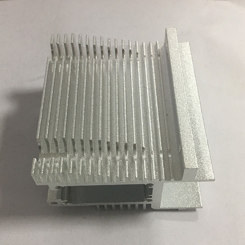
High-density-fin heat sink aluminum profiles, developed specifically for AI inference servers, edge-computing workstations, GPU servers and similar scenarios. High-density-fin heat sink profiles have complex cross-sections and a high tongue ratio (cantile
Product Details
High-density-fin heat sink aluminum profiles, developed specifically for AI inference servers, edge-computing workstations, GPU servers and similar scenarios. High-density-fin heat sink profiles have complex cross-sections and a high tongue ratio (cantilever-to-fin-pitch ratio), making mold design difficult and die-trial success rates low. The denser the fins, the longer and thinner the mold cantilevers become; during extrusion the metal impact concentrates at the root of the cantilever, and without care this leads to broken fins, tilted fins and unfilled fin tips. The key to mold design is to reduce the impact on the cantilever during metal forming through reasonable metal distribution and flow-rate adjustment.
This product focuses on the core needs of air-cooled heat sinks — "high heat-dissipation density, low air resistance and high forming precision" — and provides a one-stop custom mold-development service from fin topology optimization, CAE metal-flow simulation, mold development and isothermal extrusion to precision deep processing.
01 Quality Starts with Raw Materials
Produced from A00 primary aluminum ingot with no scrap aluminum; the thermal conductivity is stable and the heat-dissipation performance of same-batch products is highly consistent. For conventional air-cooling scenarios, 6063-T5 aluminum alloy is chosen for good formability and high cost-performance; for high-power scenarios, 1070 pure aluminum series can be chosen for better thermal conductivity, improving heat-dissipation performance by over 10%; for heavy-load installation scenarios, 6061-T6 high-strength aluminum alloy is chosen for high rigidity and resistance to deformation.
02 CAE Simulation and Dedicated High-Density-Fin Mold Design
Given the complex cross-section and high tongue ratio of high-density-fin heat sink profiles, CAE metal-flow simulation is used to optimize the fin topology and mold flow channels, reasonably distributing the metal flow rate and reducing the impact on the cantilever during extrusion. Each high-density-fin cross-section has its own dedicated mold. Molds are made of H13 hot-work tool steel and formed by vacuum heat treatment, ensuring fin accuracy and mold life.
03 Isothermal Extrusion and Precision Forming
Isothermal extrusion is used to achieve complex fin structures with ultra-thin fins and a large aspect ratio; the minimum fin thickness can reach 0.5mm, the maximum fin height is 60mm, and the fin-height ratio can reach up to 15:1. The fins are uniform and free of broken or tilted defects, ensuring an even and unobstructed air duct. Fin-thickness deviation is controlled within ±0.03mm, with no fin-collapse or material-shortage defects in forming. Fin straightness is ≤0.3mm/m and substrate flatness is ≤0.05mm/100mm.
04 Low-Stress Stable Process
A strict two-stage constant-temperature aging process is applied to fully release the internal residual stress of the profile, so that substrate warpage after machining is minimal. Substrate flatness is ≤0.05mm/100mm, ensuring the heat sink fits tightly against the chip and effectively reducing contact thermal resistance.
05 High-Precision CNC Machining
Equipped with five-axis CNC machining centers and other precision equipment, it can complete deep-processing steps on high-density-fin heat sinks such as fin-top precision milling, substrate-plane precision grinding, drilling and tapping of mounting holes, and heat-pipe channel machining. Machining accuracy is ±0.01-0.005mm; multiple imported machines and extra-long aluminum profile machining centers have a travel of up to 6.5 m.
Machining capability parameters:
| Item | Parameter / Description |
|---|---|
| Application Scenarios | AI inference servers, edge-computing workstations, GPU servers, 5G base-station AAU, high-power LED |
| Available Materials | 6063-T5 high-thermal-conductivity aluminum alloy, 1070 pure aluminum series, 6061-T6 high-strength aluminum alloy |
| Executive Standard | GB/T 6892-2023 high-precision grade |
| Cross-Section Range | Width 30mm-400mm |
| Fin Structures | Comb fins, staggered fins, pin fins, inclined fins and other fin shapes |
| Min. Fin Thickness | 0.5mm |
| Max. Fin Height | 60mm |
| Fin-Height Ratio | Up to 15:1 |
| Fin-Thickness Tolerance | ±0.03mm |
| Fin-Pitch Tolerance | ±0.05mm |
| Mounting Datum Surface Tolerance | ±0.05mm |
| Substrate Flatness | ≤0.05mm/100mm |
| Fin Straightness | ≤0.3mm/m |
| Surface Treatment | Natural-color anodizing, black anodizing, high-radiation heat-dissipation coating, conductive oxidation |
| Deep-Processing Support | CNC precision cutting, drilling and tapping, substrate precision grinding, deburring, heat-pipe channel machining |
| Mold Development Lead Time | Sampling in 7-10 days for conventional structures |
| Batch Lead Time | 10-15 days after sample confirmation |
| MOQ | Supports 50kg-level R&D sampling |
| Production Location | Qingpu, Shanghai |
High-density-fin heat sink selection guide:
| Application Scenario | Recommended Material | Recommended Fin Type |
|---|---|---|
| Air cooling for AI inference servers | 6063-T5 | High-density comb fins |
| Air-cooled modules for GPU servers | 6063-T5 / 1070 pure aluminum | Staggered fins |
| Edge-computing workstations | 6063-T5 | Pin fins |
| Heat dissipation for 5G base-station AAU | 6061-T6 | Inclined fins |
| High-power LED heat sinks | 6063-T5 | High-density comb fins |
Typical Application Scenarios:
-
Air-cooled heat sinks for AI inference servers
-
Heat sinks for edge-computing workstations
-
Air-cooled modules for GPU servers
-
Heat-dissipation profiles for small and medium computing stations
-
Heat dissipation for AI industrial vision equipment
-
Heat sinks for 5G base-station AAU
-
High-power LED heat sinks
-
Heat-dissipation profiles for communication equipment
-
Heat sinks for industrial control equipment
FAQ (Frequently Asked Questions)
Q1: What is the difference between high-density-fin heat sink aluminum profiles and ordinary heat sink profiles?
A: High-density-fin heat sink profiles have thinner fins, smaller fin pitch and a larger fin-height ratio — the minimum fin thickness can reach 0.5mm and the fin-height ratio can reach up to 15:1, placing more cooling fins on a limited substrate area and increasing the heat-dissipation area by over 40% compared with ordinary profiles. However, high-density-fin mold design is difficult: the denser the fins, the longer and thinner the mold cantilevers become, and during extrusion the metal impact concentrates at the root of the cantilever, easily causing broken fins, tilted fins and unfilled fin tips. Our company uses CAE metal-flow simulation and isothermal extrusion to effectively solve the high-density-fin forming challenge, controlling fin-thickness deviation within ±0.03mm.
Q2: What fin-height ratio can high-density-fin heat sink profiles achieve?
A: The fin-height ratio can reach up to 15:1 (fin height 60mm / fin thickness 0.5mm). A high fin-height ratio means a larger heat-dissipation area over a limited substrate area and higher heat-dissipation efficiency. But the larger the fin-height ratio, the longer and thinner the mold cantilevers, and the harder the extrusion. Our company optimizes the fin topology and mold flow-channel design, reasonably distributing the metal flow rate and reducing the impact on the cantilever during extrusion, ensuring the forming quality of high-ratio profiles.
Q3: Which materials can be selected for high-density-fin heat sink profiles?
A: For conventional air-cooling scenarios, 6063-T5 aluminum alloy is chosen for good formability and high cost-performance; for high-power scenarios, 1070 pure aluminum series can be chosen for better thermal conductivity, improving heat-dissipation performance by over 10%; for heavy-load installation scenarios, 6061-T6 high-strength aluminum alloy is chosen for high rigidity and resistance to deformation. Produced from A00 primary aluminum ingot with no scrap aluminum; the thermal conductivity is stable and the heat-dissipation performance of same-batch products is highly consistent.
Q4: What is the minimum fin thickness achievable for high-density-fin heat sink profiles?
A: The minimum fin thickness can reach 0.5mm, with fin-thickness deviation controlled within ±0.03mm. The thinner the fins, the more cooling fins there are and the larger the heat-dissipation area, but the longer and thinner the mold cantilevers, and the harder the extrusion. Our company uses isothermal extrusion and precision mold design to ensure the forming accuracy of ultra-thin fins, free of broken fins, tilted fins and collapsed fins, and to keep the air duct even and unobstructed.
Q5: What is the mold-development lead time and lead time for high-density-fin heat sink profiles?
A: The mold-development lead time for conventional structures is 7-10 days for sampling, and batch delivery is 10-15 days after sample confirmation. Because high-density-fin heat sink profiles have complex cross-sections and difficult mold design, it is recommended to discuss the fin structure (comb fins, staggered fins, pin fins, inclined fins, etc.) and heat-dissipation requirements in advance.

GET A QUOTE
Once you have submitted your requirements, we will contact you as soon as possible regarding your product inquiry.:Custom Mold Development for High-Density-Fin Heat Sink Profiles